
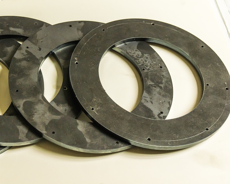
The four original drive wheels from the parts engine had been machined to a thickness very close to the minimum of 0.750 inch. The four castings I purchased cleaned up at 0.900 +/-0.005 inch. I decided to bolt and epoxy a plate onto the front of the thin wheels and machine them to match the 0.900 thick wheels. Luckily, I found 1/4 inch thick washers – 7 inch OD x 4-1/2 inch ID – made of A36, on Ebay for only $7 a piece. They appear to have been cut out of flat plate with a laser.
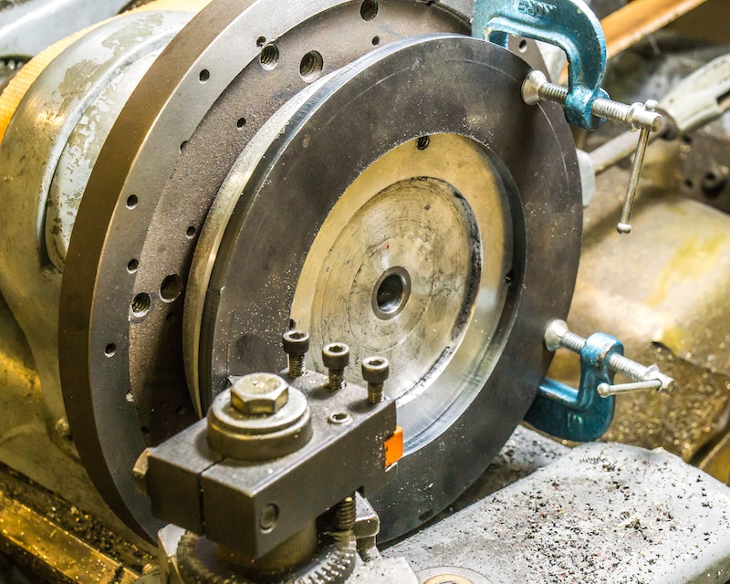
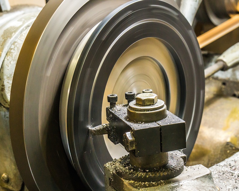
I mounted one of the thin wheels on a face plate on my lathe and indicated it to less than 0.005 inches, circular runout. I took a light face cut and marked the center of the face, turning the face plate by hand. The diameter of the bolt circle measured 6-7/16 inches.
I then marked the face plate without moving the tool in or out. Finally, I carefully marked the same line on one of the washers.
There are probably 1,001 ways to lay out a bolt circle on a part. This is how I did it.

The first step was to use a center gauge on a combination square to mark 2 holes 180 degrees apart. I then consulted Machinery’s handbook for the formulas I needed to find the rest of the holes.
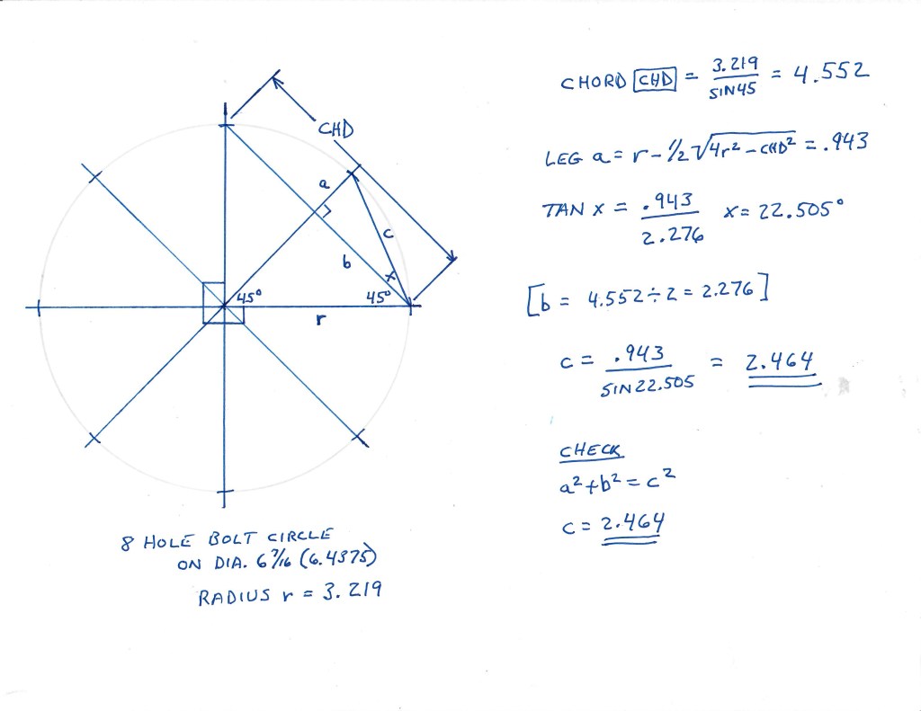

Once I determined the length of the chord for the 2 holes 90 degrees to the first two, I used calipers and dividers to carefully mark the locations. I then calculated the length of the shorter chord for the holes at 45 degrees. I carefully center punched the locations of all 8 equally spaced holes.
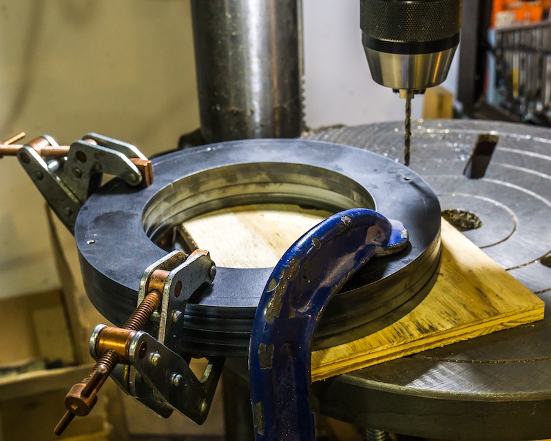
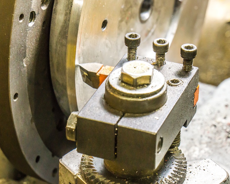
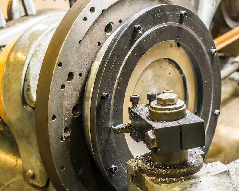
I used a center drill and then a Number 35 tap drill for 6-32 threads. I placed one part on the faceplate, lining up the holes with the scribed circular line. I clamped the part in place and match drilled the 8 holes. I put a small mark next to one hole and a corresponding mark on the faceplate, in case the holes were not really equally spaced. I tapped the faceplate for 6-32 threads and then drilled out the holes in the parts with a Number 26 clearance drill. The holes DID come out equally spaced!
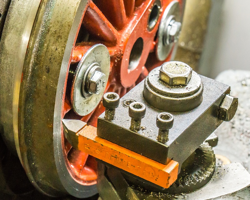
There is a lot of extra material on the ID of these washers. I cut a trepan 1/8 inch deep on both sides of the parts mounted on the faceplate.


Looks Good Tim
LikeLike