
The photo above shows four drivers with the crank pins installed. In addition to pressing them in with a 12 ton hydraulic press, they are secured on the back of the wheel with a bronze washer and epoxy. The pins were turned to the Allen Models drawing for the consolidation pins with a few exceptions. The main drivers on 2-8-0s are the third set. The main drivers on 4-8-0s are the second set – longer and larger to accept the main rod attached to the pistons, as well as the side rods. I made the left side pins 1/4 inch longer to allow for changing the gauge from 7-1/4 to 7-1/2 inches and vice versa. Split bushings are mounted on the drivers in the background in the above photo. There will be similar bushings on the ends of the left hand axles.

The horizontal mill set up for milling and drilling set screw holes on the movable left hand drivers, for changing gauge.
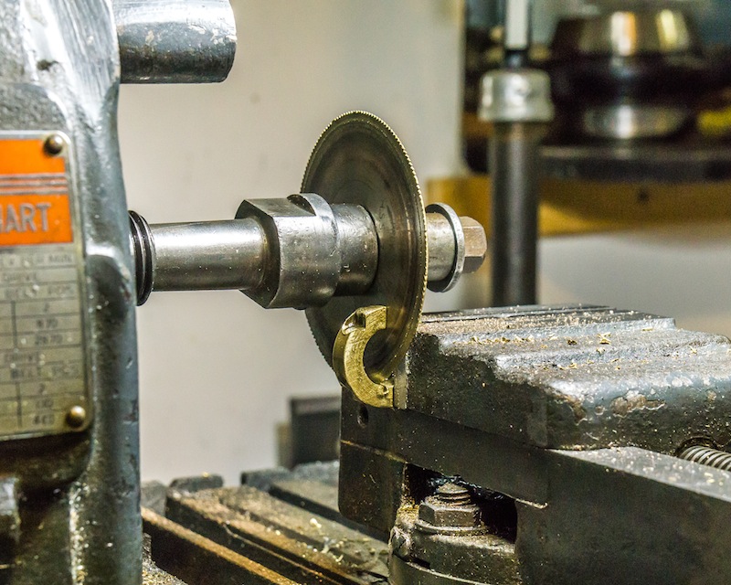
Sawing a gauge changing split bushing for one of the crank pins.

Looks good Tim,
Keep up the good work!
Dave
LikeLike