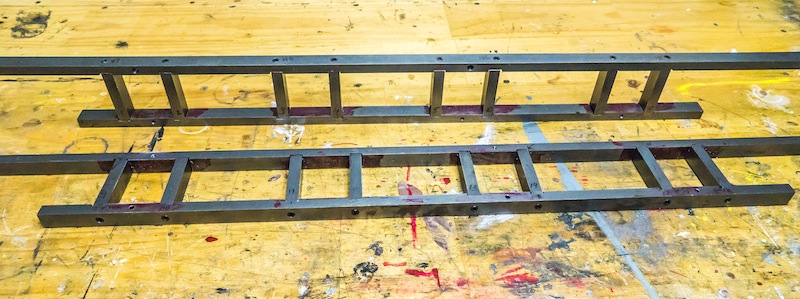
The basic frame members are 1/2 x 3/4 inch cold rolled steel, fastened together with No. 10-32 socket head cap screws. I will be spending several weeks making parts for: the spring rigging; the brake rigging; valve gear supports; cross bars; and other parts to finish the chassis.
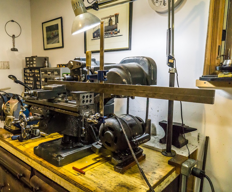
I had to rotate my milling machine 90 degrees so the long frame parts would not hit the wall. Left and right members were screwed together. so the slots would be in the same position on each side of the frame. Unfortunately, I could not accurately machine the slot locations. I laid the locations out with scribed lines and eyeballed the location of the milling cutter for each slot. In some cases I had to go back and make the slots a little wider to make the assembly work. I made the side rods first because I could machine those parts accurately.
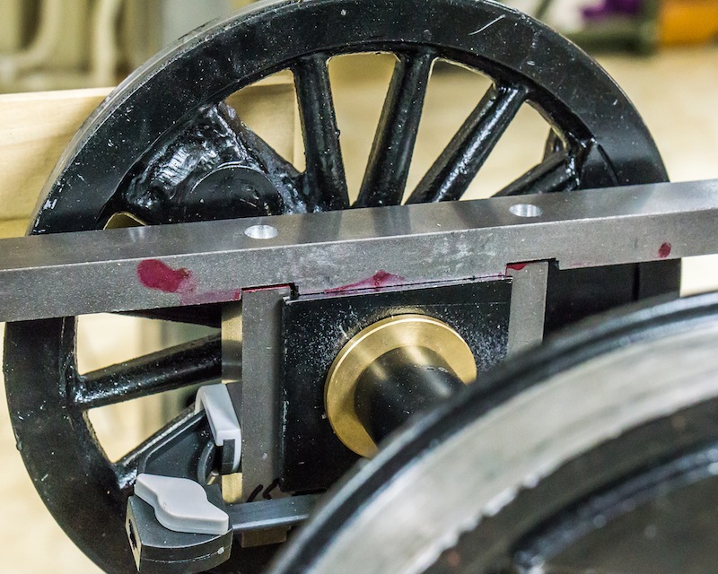
I put the wheels in their proper positions by temporarily attaching the side rods. I then clamped the side pieces against the bearing blocks (a .010 thick brass shim was inserted between the bearing block and the side piece, on both sides). I located the position of the hole to be tapped in the side pieces from the previously drilled holes in the top frame member. After a test fit of the top and side pieces on the bearing blocks, I attached the bottom frame member. I suspect it is going to be loads of fun assembling the whole mess when the rest of the parts are attached to the frame!
