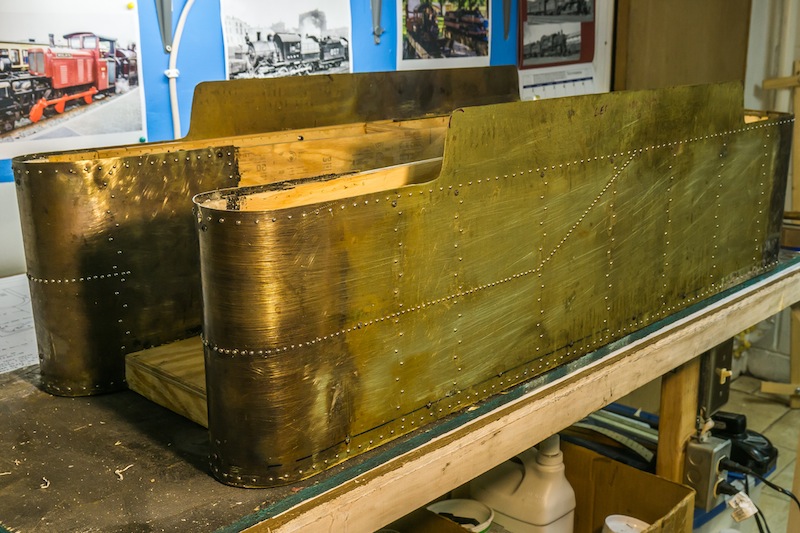
The tender is made of brass sheet lined with plywood. The interior will be covered with fiberglass and epoxy to make it water tight.

After the brass was cut to size and shape and the rivet holes were drilled, I started bending the front and rear curves using a rolling machine.

The brass had to be annealed several times as I worked the metal to get the desired radii.


I used a hard rubber mallet on a plastic pipe and one of the steel upright posts in my basement with a hard plastic mallet to help form the radii. I eventually got the metal formed to the desired shape and size.
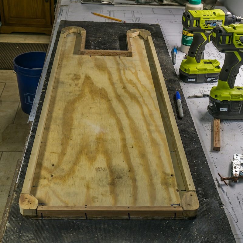
The base was made of exterior plywood. The edges were made of strips of oak and poplar, glued and screwed to the plywood.
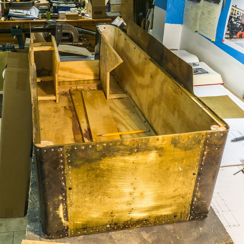
After I screwed and glued the sides to the plywood base, I decided to make the body one inch wider. I cut the plywood in half and glued a strip of plywood in between. A broader strip of plywood was glued and screwed to the top of the joint. I used urethane glue for the brass to wood and epoxy for the wood to wood splice.
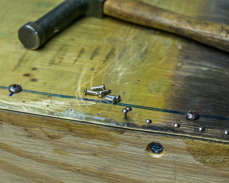
I used 0x1/4 “screw nails” to simulate the rivets. In places there are #2-56 and #5-40 button head machine screws holding some of the pieces together. I have a prototype drawing of a Norfolk & Western 12,000 gallon tender (reprint from the N&W Historical Society). The N&W used 1/2 inch shank rivets to hold the plates together on that tender. My button head screws are a little too large for a scale rivet and the screw nails might be slightly small. The prototype drawing used many more rivets spaced much closer together than on my model. The CNJ prototype I am modeling probably used larger rivets. The photos I have only show them really close together on the line corresponding to the sides of the coal bunker. I spaced the rivets on my model to give the impression of the CNJ tender, but not necessarily an exact model.
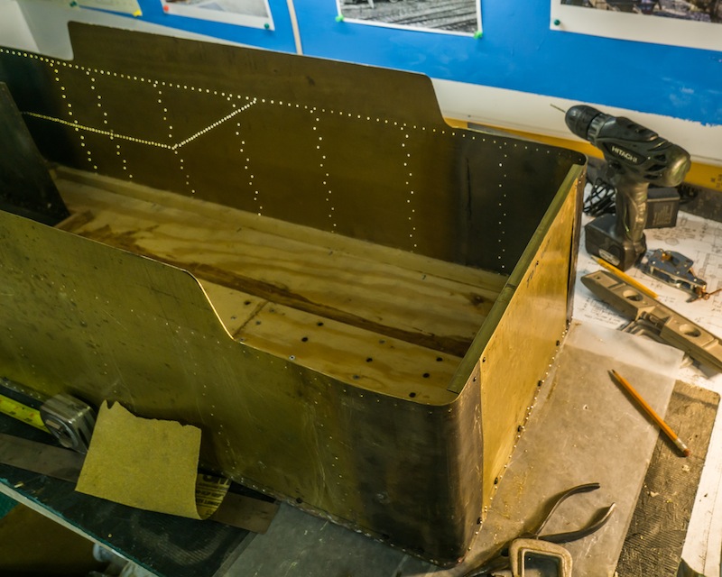
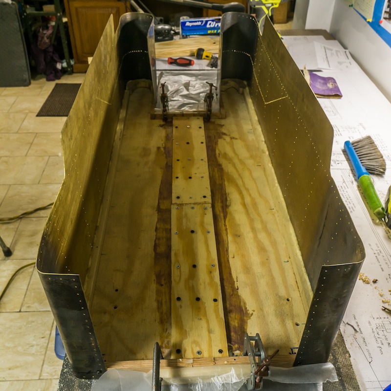
The rear of the tender is a rectangle of brass sheet. I screwed a brass angle to the inside edge of the rear and the sides up to the coal bunker. The angle will support the top piece behind the coal bunker.
The inside of the tender body was lined with plywood, dowels in the rear corners and half pieces of plastic pipe in the front curves.

A baffle and support piece of plywood was installed under the location of the engineers seat. All of the decorative screw nails were installed last. The next step will be lining the interior with fiberglass and epoxy to make a water tight tank.

Beautiful work! I’m about to start work on my Shay tender and you have given me some good construction ideas!
LikeLike