I mentioned earlier in this blog reasons why it is a good idea to design and manufacture equipment that will accommodate both 7-1/4 and 7-1/2 inch gauges.
I am making the frames narrow enough for 7-1/4″ gauge; and the cylinder spacing wide enough for 7-1/2″ gauge. I made 1/4″ wide split bushings for the axles and the cranks.


The bushings I made are split all the way through so they can be taken off the engine and re-positioned after the wheel has moved in or out.
Will this work? I hope so…I guess I will find out…
Will it be easy? Probably not. I imagine after the gauge has been in one position for a few years, it will be a pain to change the gauge, but a little cursing is a whole lot easier than major surgery!
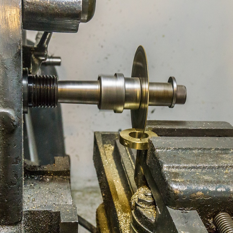
The procedure for making the bushings is:
- Turn the O.D., I.D., and thickness to size.
- Mill corners for the screw heads.
- Center drill and tap drill two holes parallel to each other on either side of the center bore.
- Slice the bushing in half perpendicular to the drilled holes.
- Tap the bottom half of the bushing.
- Clearance drill the top half of the bushing.
- On the axle bushings, broach a keyway slot perpendicular to the cut half.
Material dimensions:
- Axles and main crank: 1.5″ O.D. x 0.75″ I.D. x 0.25 thick. Socket head cap screws are No. 6-32 x 5/8″.
- Three cranks: 1.188″ O.D. x 0.625″ I.D. x 0.25″ thick. Socket head cap screws are No. 5-40 x 3/8″.
I used brass and I made extras while I had everything set up.