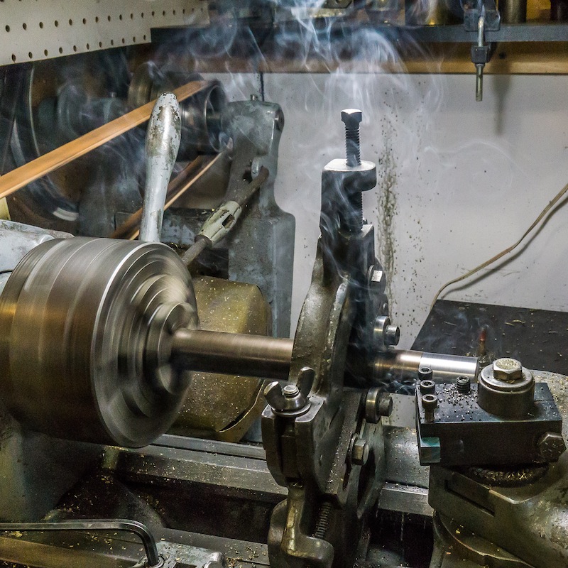
I machined the four main axles out of one inch diameter 1144 (stress proof) steel. The right hand side will be pressed onto the wheels with an interference fit. The left hand side is 1/4 inch longer than the right side to accommodate changing gauge (7-1/4 and 7-1/2).

The axle stock is mounted in the lathe with the steady rest near the end. I used an indicator to adjust the runout on the end of the axle to a couple of thou.
I machined the ends to fit the wheels and bearings. Put unique witness marks on all mating parts, to make assembly easier after painting.

The “back to back” dimension on the wheel sets is critical to their function. I set that dimension for 7-1/4 inch gauge. A split spacer will be added behind the wheel to make the wider 7-1/2 inch gauge.

The axles are now ready to cut the keyways in the ends to quarter the drivers.
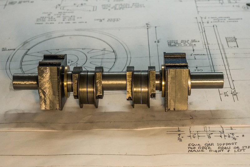
The eccentrics from my “parts engine” could only be bored to 7/8 inch, so I modified the main axle by turning most of it to that dimension. The bearing on the right hand side butts up against a retaining ring.
