The cast smokestack from Allen Models is too tall for my engine because the Wooten firebox has to sit above the drivers. The distance from the rail to the top of the stack on the prototype when built was 14 feet, 11 inches. That was reduced to 14 feet, 9-1/2 inches when the engines were rebuilt due to close clearances in tunnels.
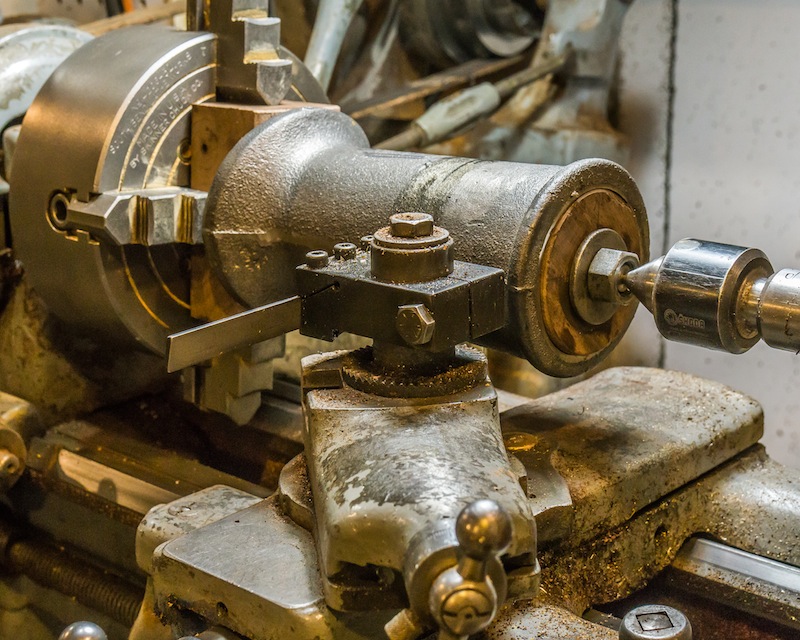
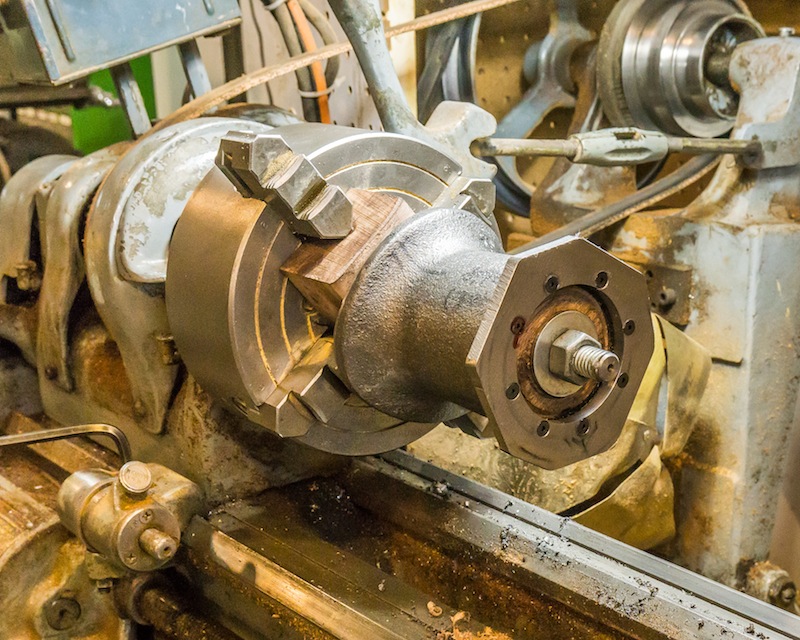
I turned a plug from scraps of walnut and bolted the stack to another piece held in a four jaw chuck so I could machine the casting. The casting is quite oval so I did not even try to clean up the outside diameter.
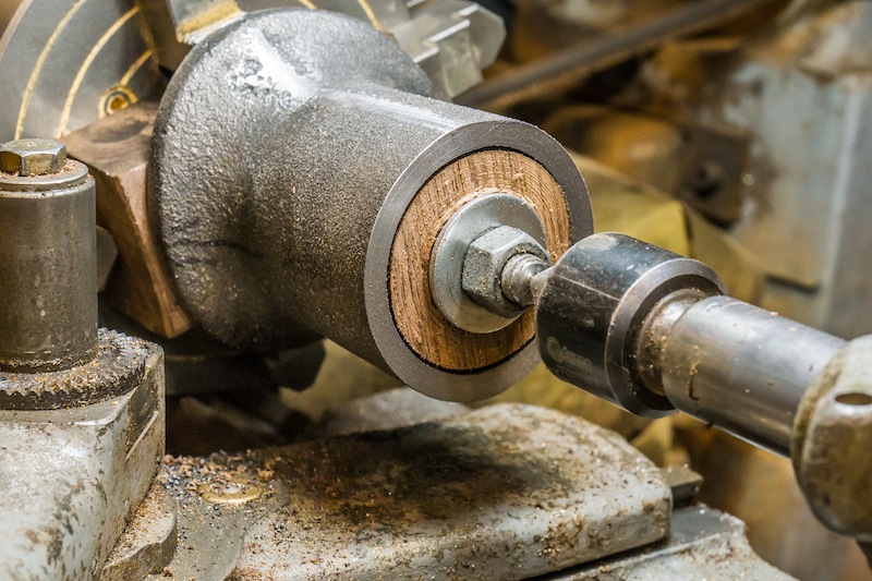
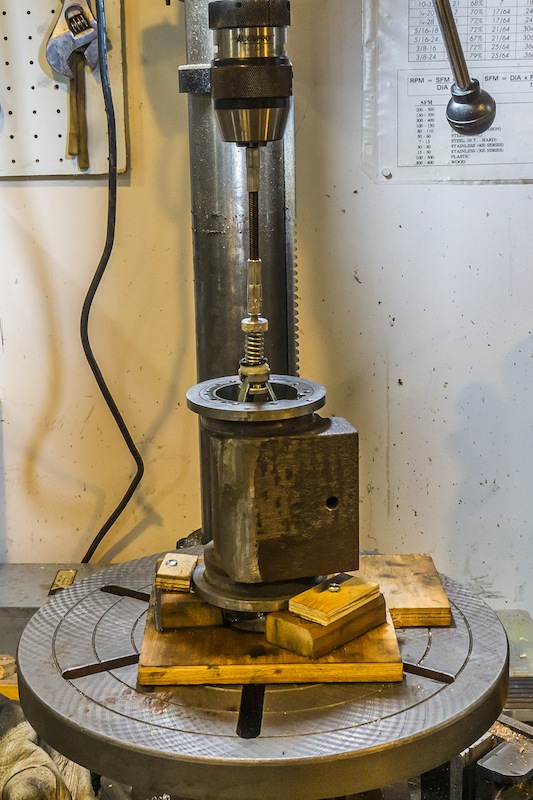
I faced the top of the stack so I could attach a new cap.
The cap is made of steel and was bolted on with #5-40 flat head screws.
I used a carbide tipped hole saw to make a 2 inch diameter hole for the stack.
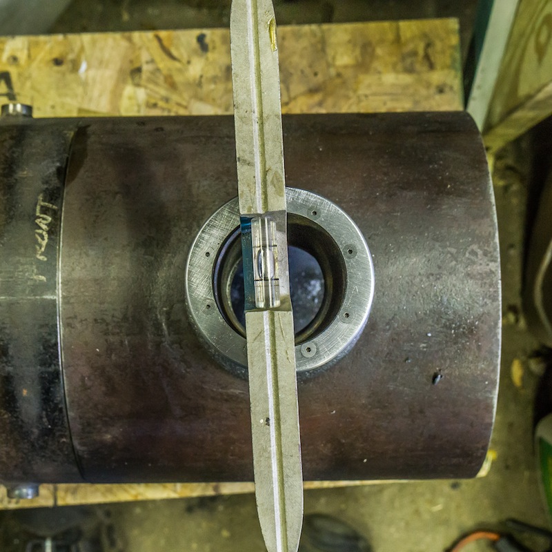
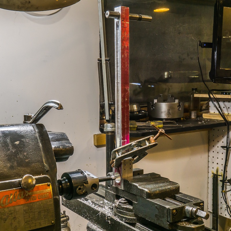
I made sure the boiler was level and then mounted the stack over the machined hole. The stack was mounted with #8-32 screws drilled and tapped into the smokebox.
The stack will be mounted with more decorative screws at final assembly. The smokebox is attached to the boiler with 4 screws on the inside edge. Now that the relationship with the boiler is correct, I will be able to duplicate this position on the chassis with the use of the level.
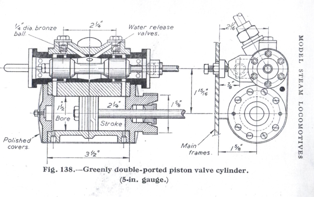
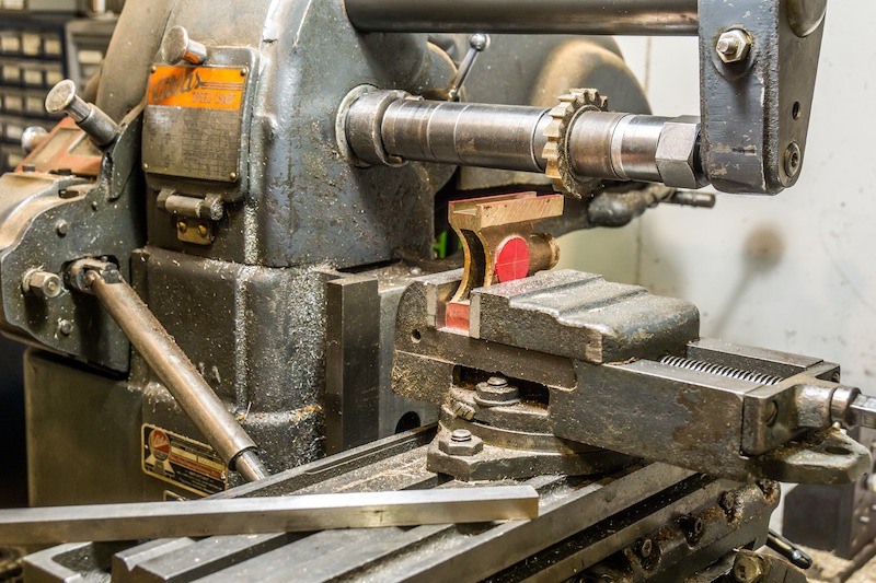
The locomotive I am building has outside pistons and inside valves. I have cast iron cylinders but I am constructing the piston valve housing from bronze tubes and copper fittings. Bronze liners will be pressed into the housing (black in the cross section above).
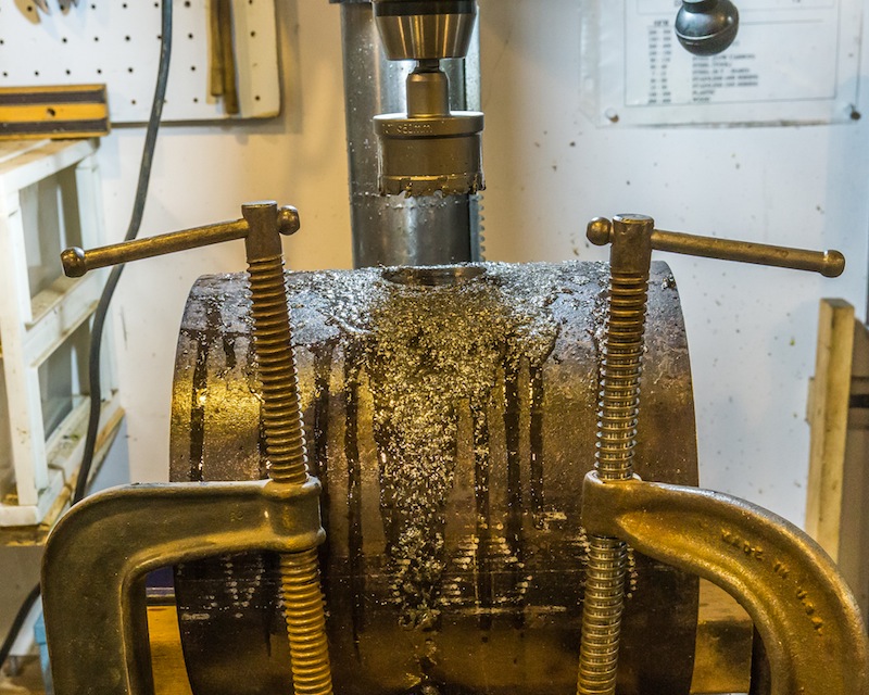
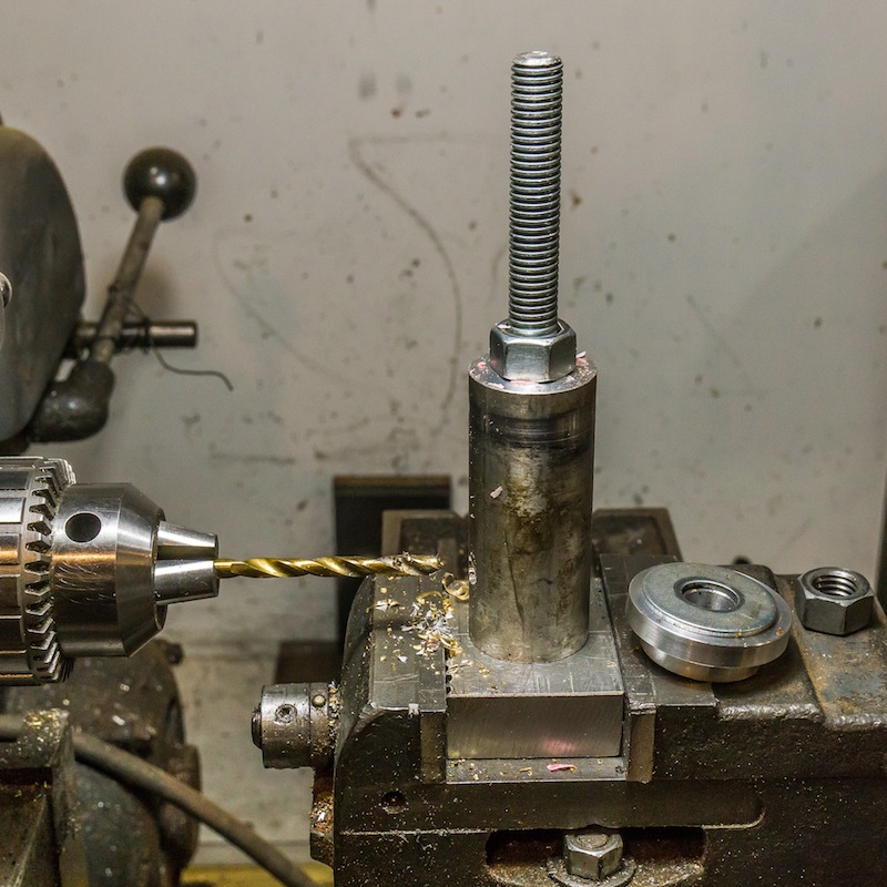
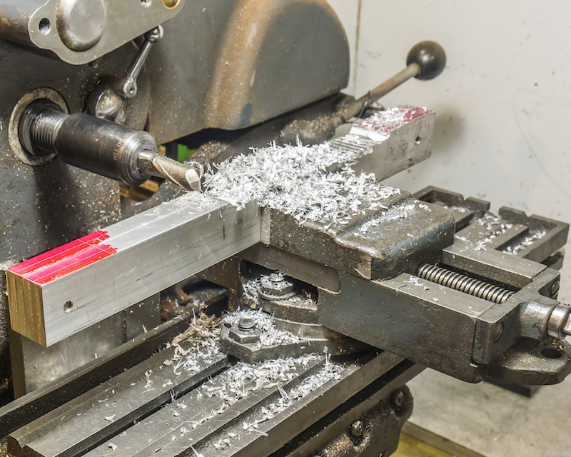
Boring the bronze tube for the valve housing.
The housings are 5-3/16 inches long; the outside diameter on the ends is 1.65 inches; the outside diameter in the center is 1.56 inches; and the inside diameter is 1.27 inches.
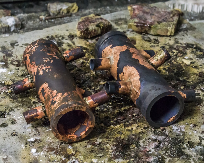
I silver brazed type K 3/8 copper tubing for the connections to the plumbing fittings. All the fittings were also silver brazed (45% silver).
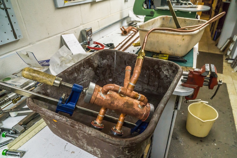
I hydro tested the housing to find leaking joints. I did have to re-braze a few of the connections.
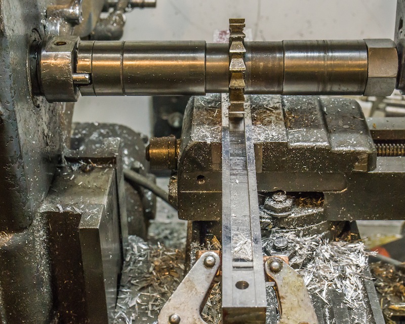
The water relief valves were cut at an angle in the housing, so I milled a flat before drilling the holes. Some of the fittings had to be “keyed” with a short piece of 1/16 inch diameter brass rod to keep them in position when brazing.
I made a simple aluminum fixture to hold the housings for milling and drilling.
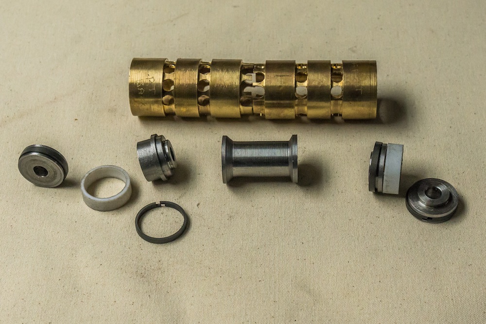
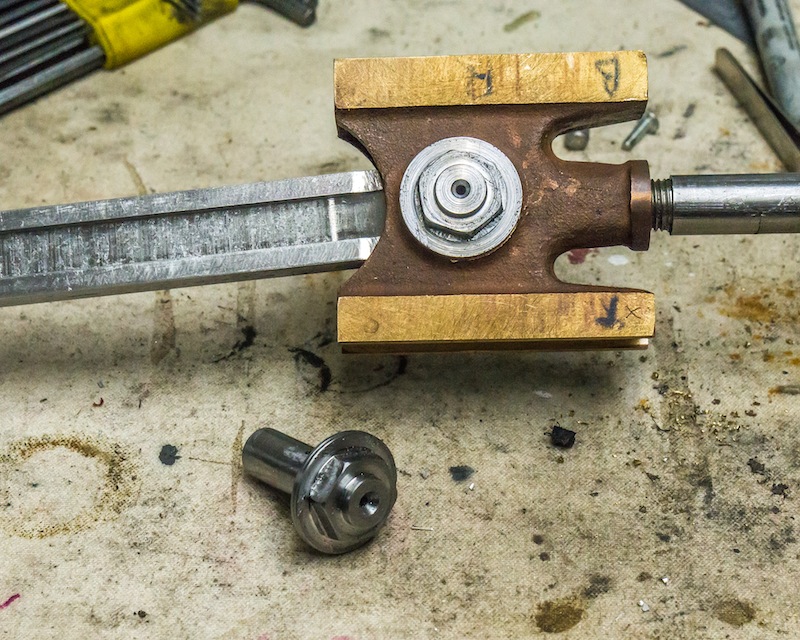
I made two inserts (left in photo above) for each hosing. They needed to be accurately bored and honed for the piston valve. If a picture is worth a thousand words, then a model is worth a thousand pictures. I made a model insert from PVC and a piston valve from a wood dowel so I could better understand how the valve functions.
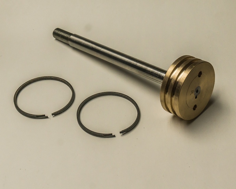
The photo above shows a pair of bronze inserts and the components for one piston. The piston is turned from 1144 stressproof steel. The iron piston rings will set the timing of the valve and the Teflon rings will keep the steam contained on the inside or the outside of the piston. The piston is hollow to allow exhaust steam to equalize on the outside ends of the piston.
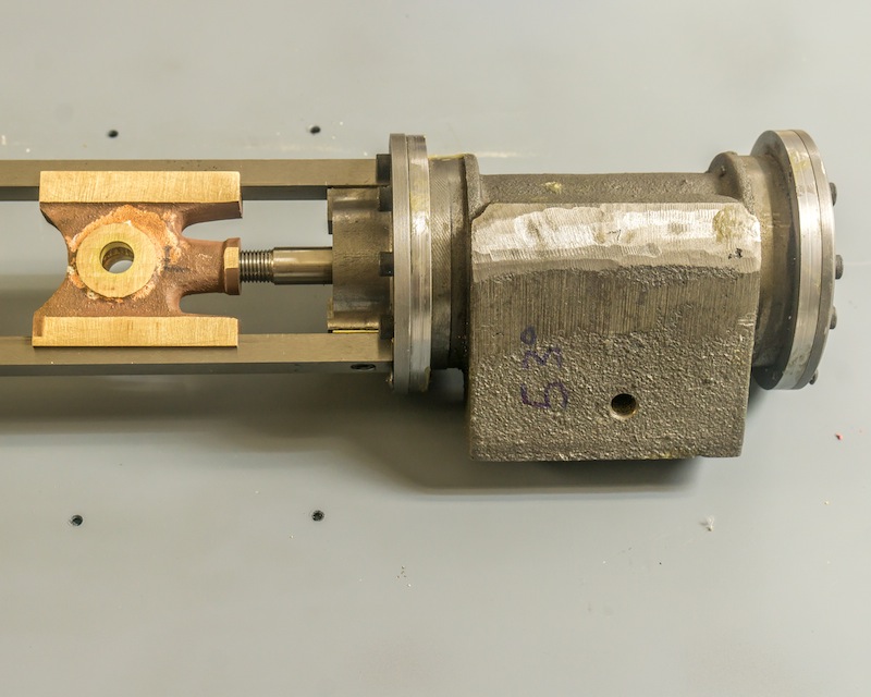
An assembled piston valve with a pair of inserts.
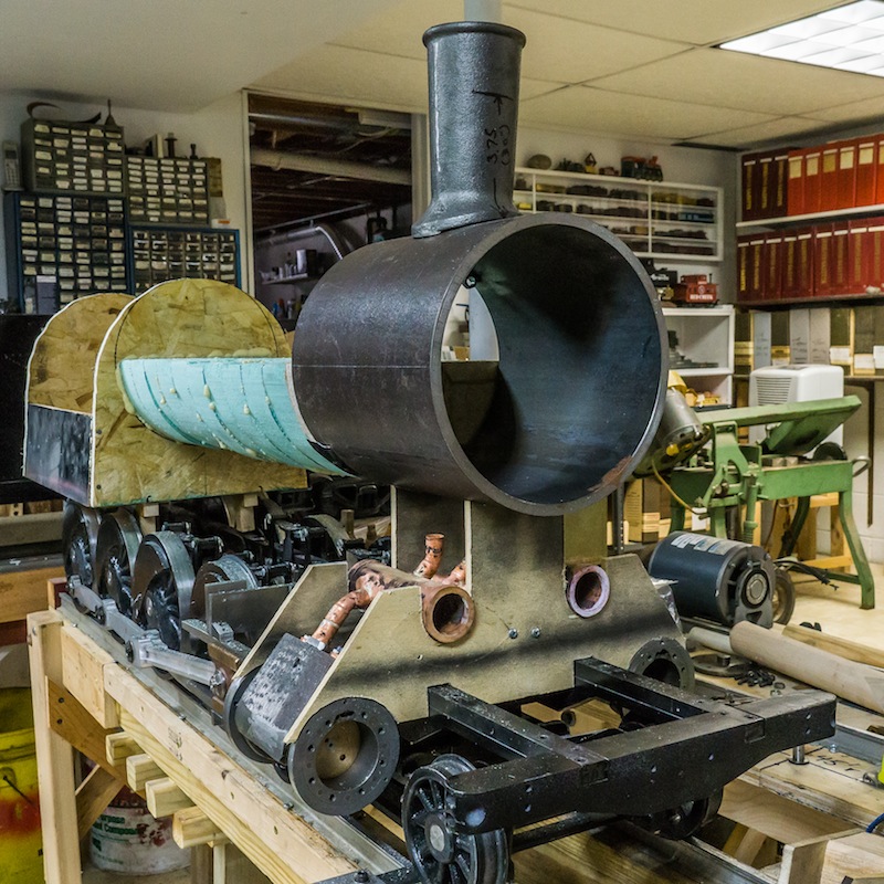
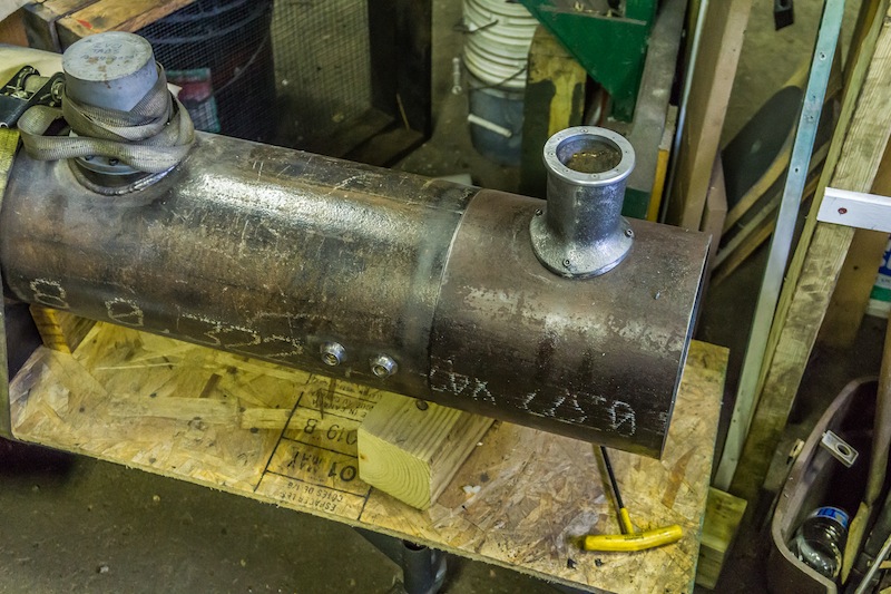
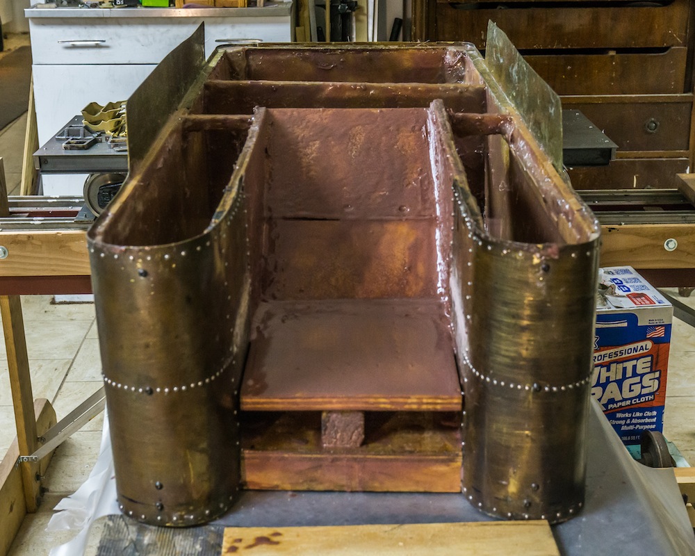
There is a lot going on around the piston valves, so I am working on multiple components at the same time. The above photo shows a mock boiler and mock plywood saddle ends along with the real smokebox. I will need to drill the bottom of the smokebox to accommodate the stem entry pipes and the steam exhaust pipes. All of that has to be assembled and tested before I press in the inserts for the piston valves. The next task will be finishing and installing the smoke stack, so I can use it to line up the smokebox for drilling the bottom .
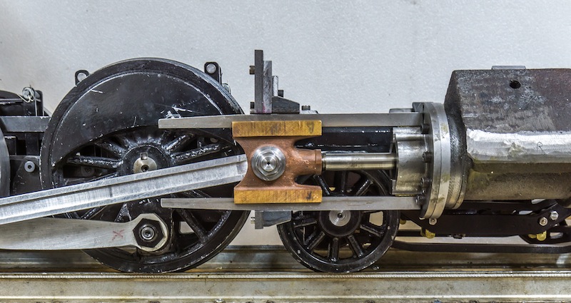
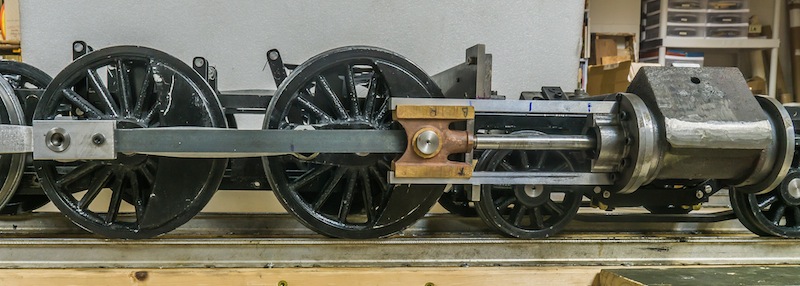
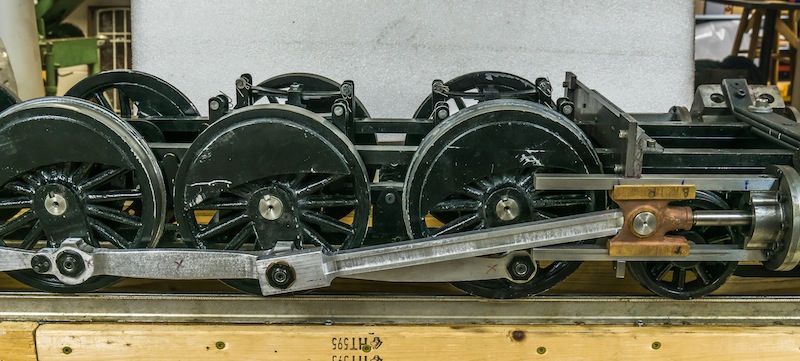
Cylinders, crossheads and main rod mounted on the frame.
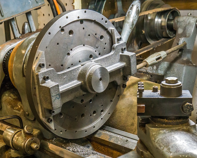
I have not written a post in about six months, but I have been busy. During the summer, I spent time maintaining and running the Shay and the “500.” In August, I strayed from trains and spent a couple of months building a Rose Engine Lathe. When the cold weather set in it was back to work on this beast.
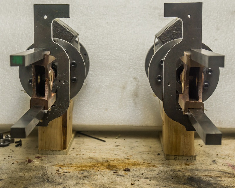
I bolted the left and right crosshead guide hangers and milled them as one piece to make sure they were identical.
Finished guide hangers.
I spent some time making sure the location of the cylinders was correct. I built a test bench with a 55 foot radius curve to make sure the engine would track without the lead truck interfering with the cylinders. I also had to try the fit in both 7.25 inch gauge and 7.50 inch gauge.
When I was sure the components were located, I drilled and tapped the cylinders for mounting. The guide bars are held in place with steel plate work. I tapered the rear section of the guides and added small blocks to help hold them in place (see the first photo).
I made a temporary two piece main rod which could be adjusted to find the proper length.
The main rods were made from aluminum bar stock, bolted together and machined as one.
Each main rod was fluted to match the prototype. Brooks Locomotive Works made the side rods plain sided and fish-bellied; only the main rods were fluted.
Boring precise holes for the crank pins required a creative setup on the horizontal mill.
The finished main rod minus fake bolts (details to be added later).
The pin holding the main rod to the crosshead was machined from one piece of 1144 stress-proof steel. A fake nut was machined in to make it look like the prototype. There are lubrication holes drilled in the center of the pins along with cross holes to get oil to the bearing.
Here is an overhead shot of the cylinders, crossheads, guides, and main rods mounted on the frame. I have already started machining the inside admission piston valves. That will be the next blog post in the near future.
It has been a while since I updated this blog, but I have been hard at work on my live steam projects. I have two steam engines in operating condition at my club – Finger Lakes Live Steamers – in Western upstate New York. Of course there is an old joke stating “steam engines are always broken.” Mine are no exception even though they are currently running well. I replaced the whistle valve on my Shay, but the brakes do not work at all! The “500” is sporting new handrails, and even though the steam brakes do work, some of the brake fittings in the cab are leaking steam.
Speaking of the “500,” I hope you all saw it featured on the cover of the May/June 2021 issue of Live Steam And Outdoor Railroading magazine. They did a really nice job of publishing my article.
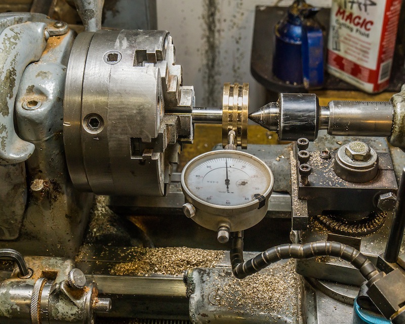
The piston rods are half inch 300 series stainless steel. It is very important to make the pistons concentric to the piston rod, so I assembled the piston blank to the rod and then turned the final dimensions as a unit. My six jaw chuck can be adjusted for runout, so I took extra time to indicate it in as close to zero as I could make it.
The iron rings were purchased from Allegheny York LLC in Manchester, PA. The ends overlap and they are very reasonably priced.
I honed the cylinders with a brake hone in the drill press before installing the pistons.
The cross heads are bronze castings from Allen Models. Milling should be straight forward but, I managed to screw things up a bit. The cross hole for the wrist pin was not bored on the center line of one casting, so I had to silver braze a bushing and re-bore it. I also did not get the slots for the guide bars central to the center line for the piston and wrist pin. That means there is an extra step of adding shims between the guide bars and the cylinder mounts at assembly.
Tapping the 7/16-20 hole for the piston rod.
Milling the crosshead slots
Final inspection – Did I get it in the right place?
The next step in this project is to get the cylinder assemblies mounted on the frame, so I can make the piston valves and attach the valve gear and rods.
The engine is a camelback, so the fireman’s space is located primarily on the front of the tender. Between several hundred train books I own and the internet, I could only find a small handful of photos illustrating the front of a tender. I do have photos of the side of the prototype, so the steps, grab irons and side gates are fairly accurate, but the doors to the coal bunker are partly from my imagination. The cast brass front steps are Reading caboose steps, but they were close enough to the CNJ steps and I had them in my collection of stuff.
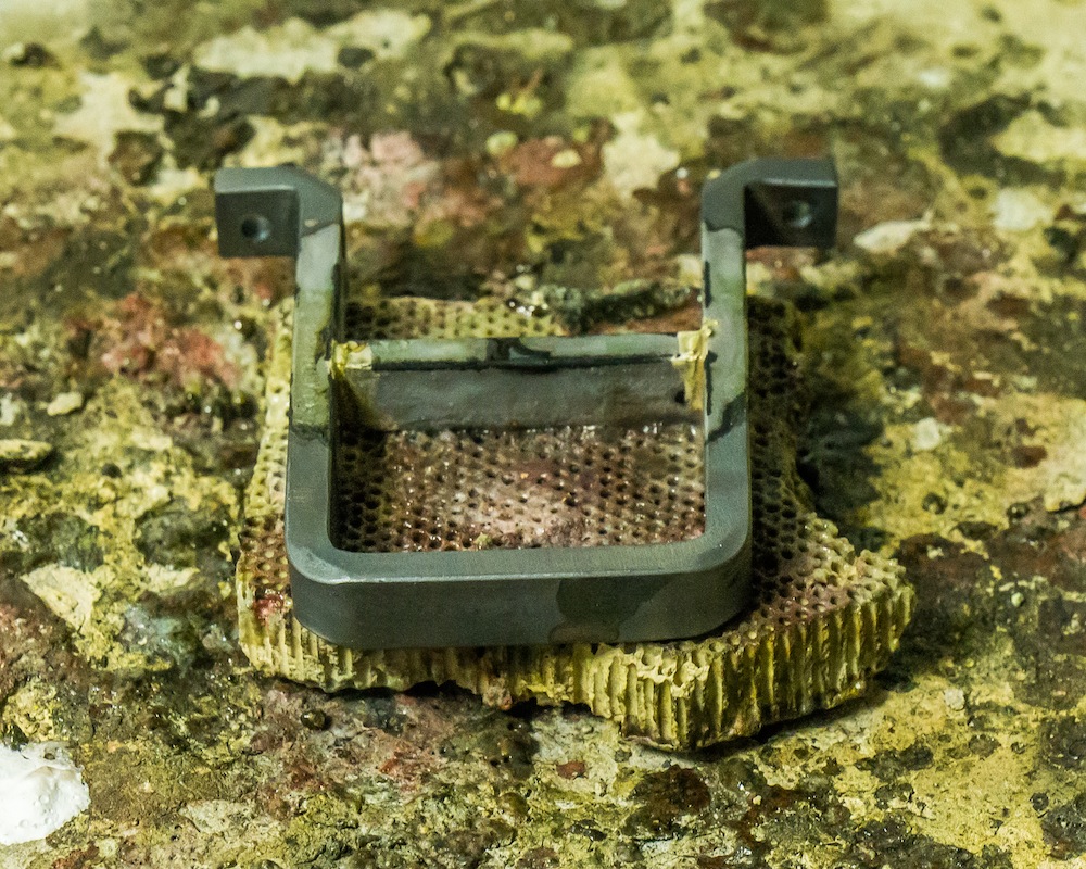
The rear steps are “stirrup” style and they were fabricated from 3/16″ x 3/8″ steel, with the rung silver brazed in place.
The corner grab irons are made from 3/16 inch diameter rod, which might be a little heavy, but the corners of the tender are likely to be abused over time, so robust details are better than lighter “true to scale” details.
The first coal bunker I made was too small and not correct to the prototype tender. I was able to surgically remove the inside walls with an oscillating multi-tool and move them out to the sides.
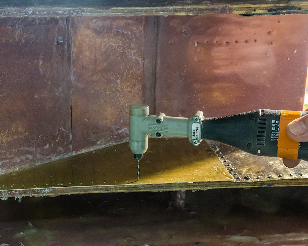
The right angle attachment for a Dremel tool is ideal for drilling out the rivet holes in tight spaces.
Once the side walls had been moved outward, the new coal bunker was made of 1/8 inch steel and scraps of brass sheet.
The coupler pocket is a casting from Allen Models. The rear ladder was constructed from steel bars and round brass rungs, silver brazed together and screwed onto the rear of the tank.
The fireman’s platform was made of steel sheet supported by brass angles.
The steps attached to the firing platform are fabricated from brass sheet. The gates feature operating hinges and locking mechanism (see top photo).
The doors to the bunker are fixed in place as shown. The plates on top of the forward water legs will eventually be drilled for valve handles. I will install the functional plumbing during the painting operation when the weather is warmer.
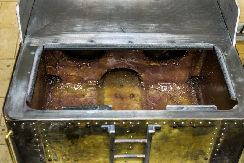
The inside of the tank has been coated with fiberglass and epoxy. It is not very attractive, but it only needs to be watertight!
The cast water hatch will allow the tank to be filled during operation. The larger plate the casting is attached to, lifts out for access to the interior of the tender. There are several small details to make and add – cut levers, poling pockets, ladder grabs,and miscellaneous hardware. I cannot do much more until the weather improves. When it does I will paint the parts I’ve made and finish the remaining details. The time has come to finish the chassis. I plan to steam the engine in 2022.
I am using the tender castings from Allen Models and following their drawings with a few minor exceptions. The drawings call for one inch wide channels for the longitudinal members. I did use one inch wide for the two internal channels, but I used 1-1/2 inch wide channels on the outside. Looking at the prototype photos, the channels below the tank are quite wide – at least as high as one of the steps. I have four investment cast brass steps designed for a Reading bobber caboose. I am going to use a pair of those for the front tender steps and the other pair will go on the engine just behind the pilot. These are not exactly prototypical for Brooks or the CNJ, but they are close and I have no other use for them. The rear tender steps will be fabricated out of bar stock.
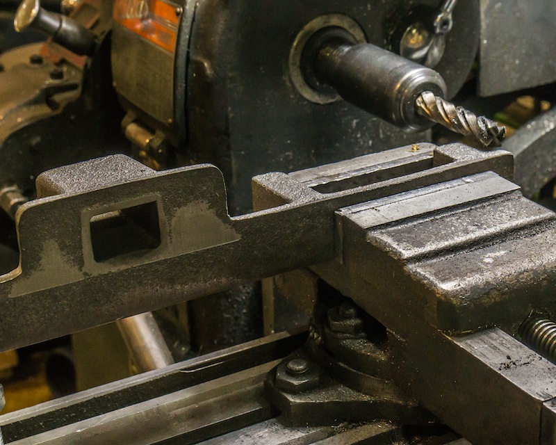
I had to use several setups to machine the castings on my small horizontal mill.
Drilling a cross hole in the internal boss was accomplished with an aircraft drill, by hand.
The truck mount castings were faced in the lathe (tight fit!).
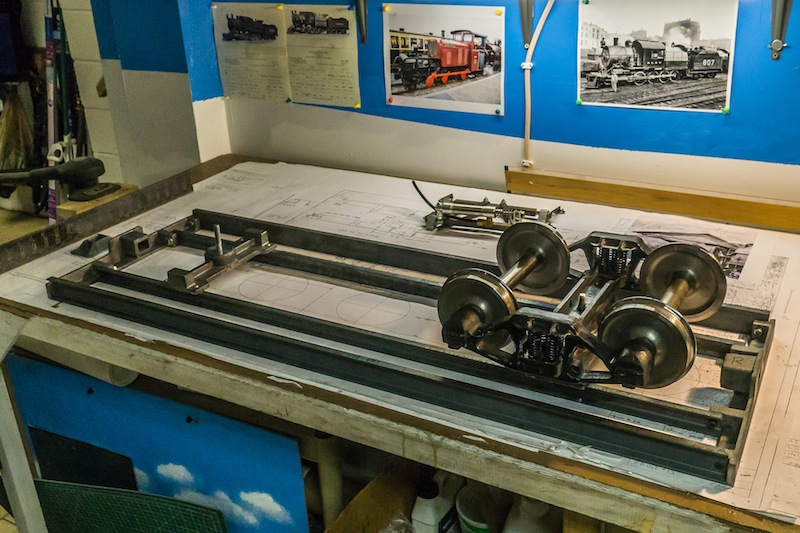
This is a temporary assembly to test the fit of the tender parts. I will finish the details and fiber-glassing the tank, but I will not be able to paint everything until next Spring (warmer weather).
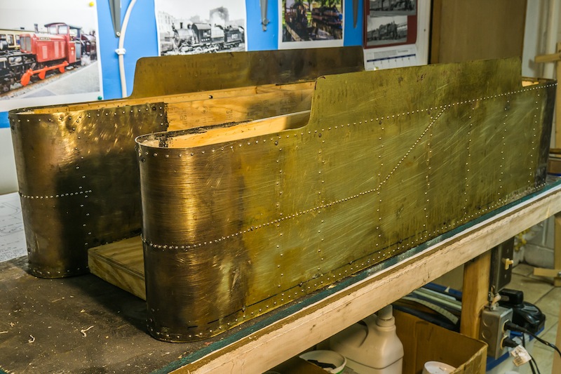
The tender is made of brass sheet lined with plywood. The interior will be covered with fiberglass and epoxy to make it water tight.
After the brass was cut to size and shape and the rivet holes were drilled, I started bending the front and rear curves using a rolling machine.
The brass had to be annealed several times as I worked the metal to get the desired radii.
I used a hard rubber mallet on a plastic pipe and one of the steel upright posts in my basement with a hard plastic mallet to help form the radii. I eventually got the metal formed to the desired shape and size.
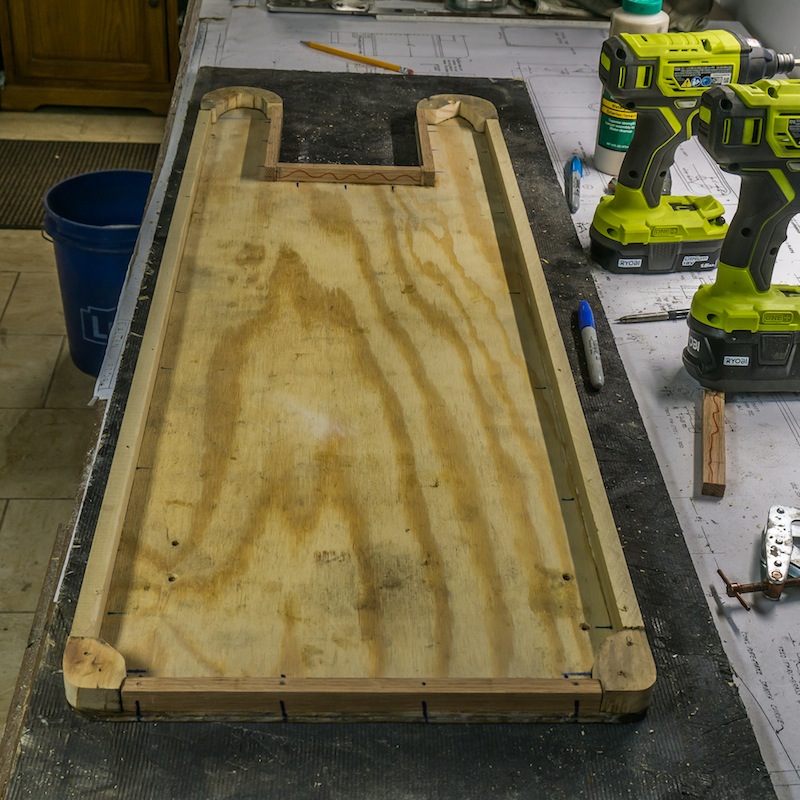
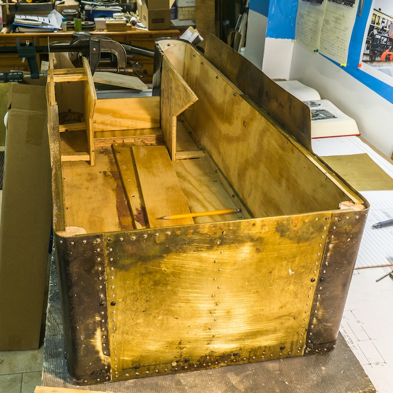
The base was made of exterior plywood. The edges were made of strips of oak and poplar, glued and screwed to the plywood.
After I screwed and glued the sides to the plywood base, I decided to make the body one inch wider. I cut the plywood in half and glued a strip of plywood in between. A broader strip of plywood was glued and screwed to the top of the joint. I used urethane glue for the brass to wood and epoxy for the wood to wood splice.
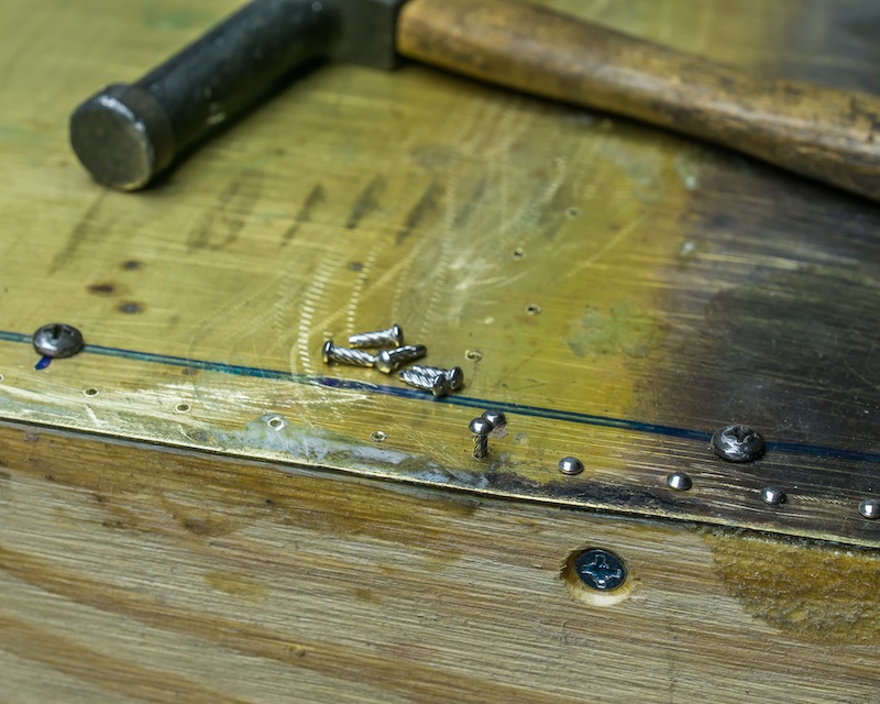
I used 0x1/4 “screw nails” to simulate the rivets. In places there are #2-56 and #5-40 button head machine screws holding some of the pieces together. I have a prototype drawing of a Norfolk & Western 12,000 gallon tender (reprint from the N&W Historical Society). The N&W used 1/2 inch shank rivets to hold the plates together on that tender. My button head screws are a little too large for a scale rivet and the screw nails might be slightly small. The prototype drawing used many more rivets spaced much closer together than on my model. The CNJ prototype I am modeling probably used larger rivets. The photos I have only show them really close together on the line corresponding to the sides of the coal bunker. I spaced the rivets on my model to give the impression of the CNJ tender, but not necessarily an exact model.
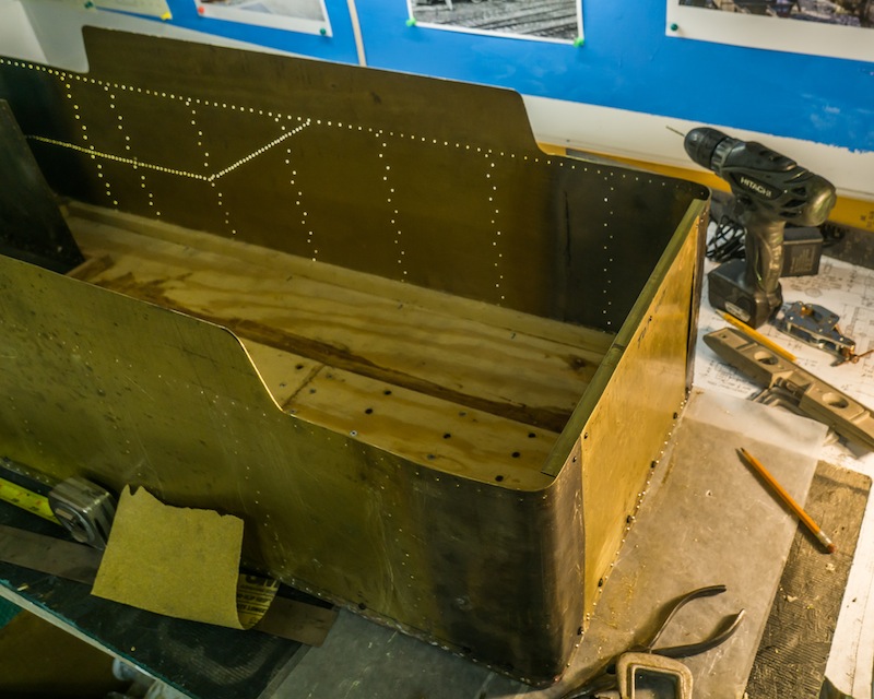
The rear of the tender is a rectangle of brass sheet. I screwed a brass angle to the inside edge of the rear and the sides up to the coal bunker. The angle will support the top piece behind the coal bunker.
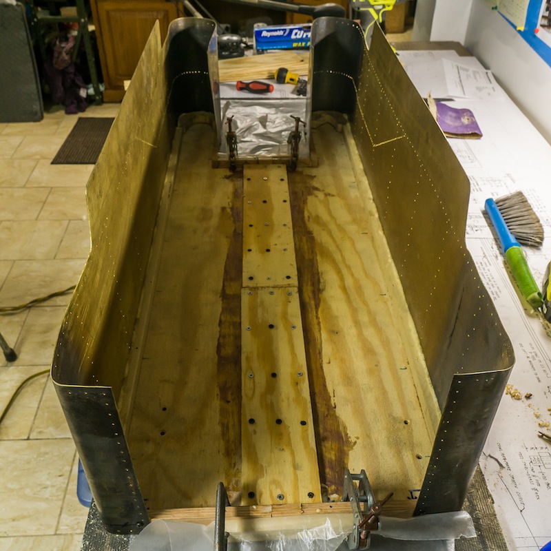
The inside of the tender body was lined with plywood, dowels in the rear corners and half pieces of plastic pipe in the front curves.
A baffle and support piece of plywood was installed under the location of the engineers seat. All of the decorative screw nails were installed last. The next step will be lining the interior with fiberglass and epoxy to make a water tight tank.
I have started building the tender for the 4-8-0 camelback. Several years ago, I was given a 6 x 2 foot sheet of brass, so that is the tender material. The prototype shown above is very close to Allen Models 33 inch tender – just a little bit taller. I will use the Allen drawing with the modified dimensions.
My electric shear is great for straight lines and broad curves, as long as you can spare a 1/4 inch wide strip of scrap.
I am using a drill mounted nibbler for the sharp radii. It takes a little practice to follow a line with the nibbler, but it does work well for thin brass and aluminum sheet metal.
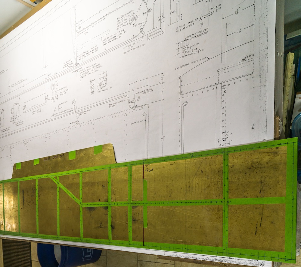
The two sides for the tender have been cut from the brass sheet. There is extra material front and back to bend around the corners. The extra material in the front will form the sides of the coal bunker. I have marked the 414 rivet holes on the side of the sheets, which have been taped together for drilling.
It has been about three months since I posted to this blog. I have not worked on building the CNJ camelback, but I have been very busy in my shop.
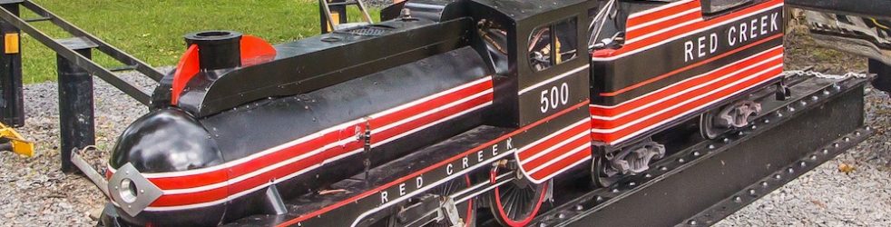
The photo above is a 4-4-0 kitbashed using parts from a Little Engines pacific in 1957 by Jim Turnbull of Montreal Canada. I am the seventh owner of this engine. When I acquired it in 2006, it needed some repair to the old copper boiler, all new plumbing, detailing, paint and quite a bit of work on the tender. I detailed it to look like the Chicago & Illinois Midland No. 500. I got it running in October of 2009.
The 2009 version of this engine
I ran the engine a lot for eight years. As with most steam engines it developed a few problems. It made quite a bit of noise because the drive train was wearing out after fifty plus years of running. At the end of the 2017 running season, I decided it was time to pull the boiler and give the drive train a complete overhaul.
I was just finishing the Shay, which I ran for the first time in the summer of 2018. I have been running the Shay every week this summer (2020). It runs on propane and has become a fairly reliable engine.
Red Creek Shay under steam at Finger Lakes Live Steamers
The reason I had decorated the engine as C&IM No. 500 was because it fit. There were not many big twentieth century Americans with piston valves. The C&IM engines were the last three 4-4-0s built by Baldwin for domestic service (1929). I decided to look at some other prototypes to make a change in the look of the locomotive. The DL&W had a streamlined 4-4-0 similar to their streamlined pacifics and ten-wheelers. Polished stainless steel wings and an odd shaped front end would be extremely difficult to model with my limited sheet metal skills.
DL&W streamlined 4-4-0
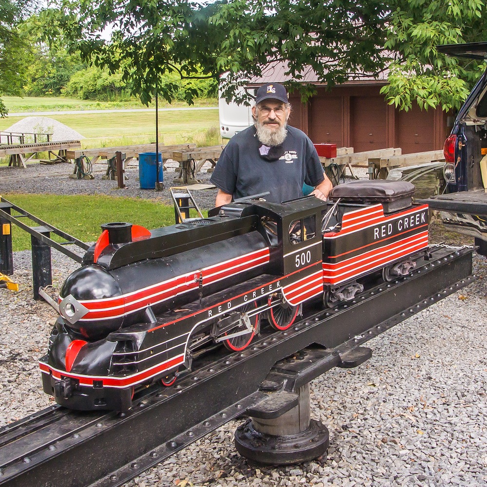
I decided to freelance the engine based upon the Lehigh Valley’s Black Diamond. I would just letter the engine for the Red Creek Railroad (same as the Shay). The first Red Creek RR was my garden railroad. The swampy area behind my house becomes a tributary of the Red Creek flowing through Henrietta, NY and eventually joining the Genesee River near the intersection of the Erie Canal.
Finally, I took the engine to the club on August 15, 2020 for its first run as a new engine. There were a few minor things to fix. One of the water tubes from the tender was too long because the plumbing had changed slightly. The grates did not want to stay in position because I did not make the shelves they sit on, wide enough. Alan Francis II and Don Jermyn helped make a shim from a piece of angle iron to fit in front of the grates.
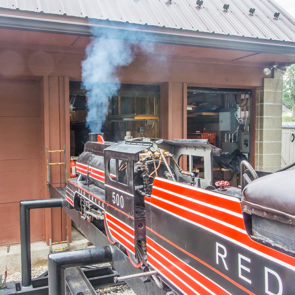
Steam Up!
I slowly opened the throttle and the engine moved onto the transfer table where the two driver sets promptly derailed!!! Fortunately help was not far away. Dave Pierce used the tractor to lift the very hot engine up enough for Alan Francis II to re-rail it while I kept an eye on the water and fire and my shoulder against the cab to keep it from tipping. That was a very scary moment! The yellow hinged section of the table had a deformed bump which allowed the wheels to ride up and off the rails. Jack Wylie removed the bump with an angle grinder, but until those hinged sections are replaced, we all need to be very careful when moving equipment on and off the table.
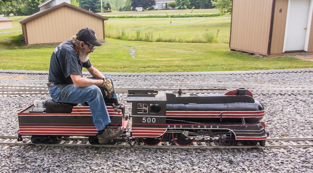
Running the newly rebuilt engine. photo by Alan Francis II
The re-railing was quick enough for the steam to only drop as low as fifty pounds. I was able to get the fire going again while still sitting on the transfer table. Now for a test run. What a great little engine! It steams very well. I am very happy with the engine and I’m sure I will be running it often!
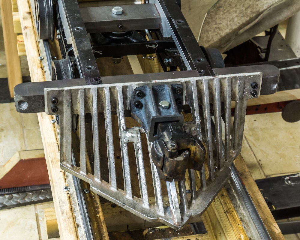
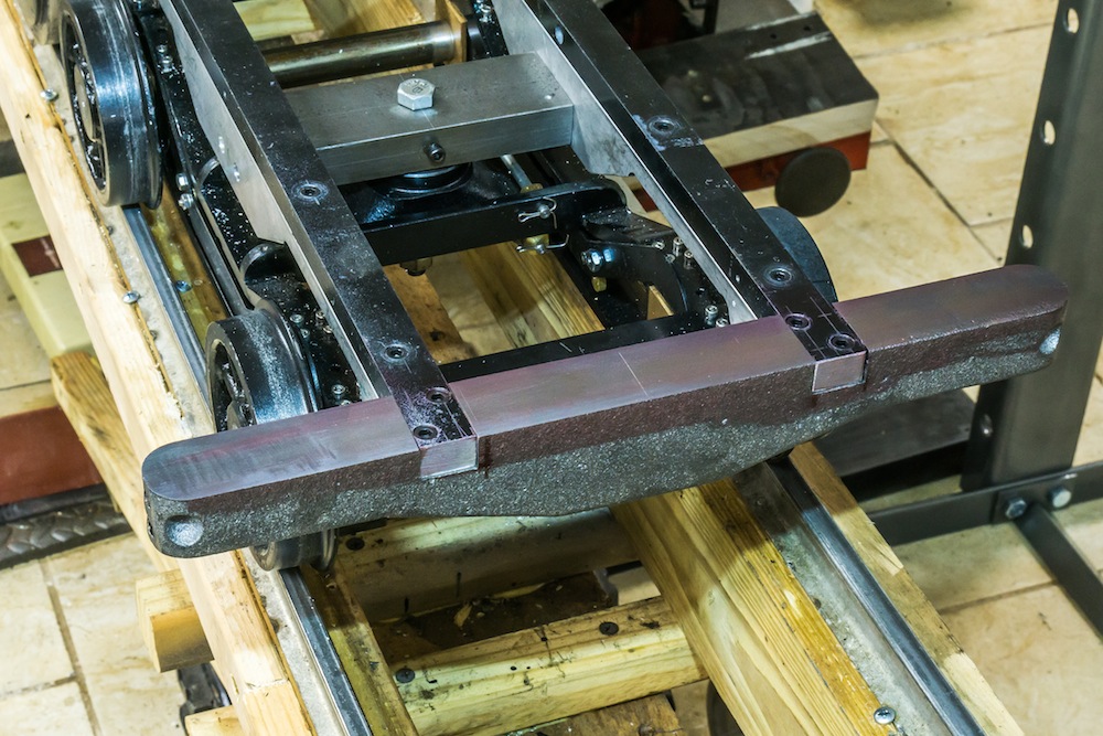
The pilot consists of a cast iron buffer beam and coupler pocket, a cast aluminum cowcatcher and the coupler. I added a three pieces of aluminum to the cowcatcher for strength and aesthetics.
The cast iron buffer beam from Allen models was milled and tapped to accept the two frame members.
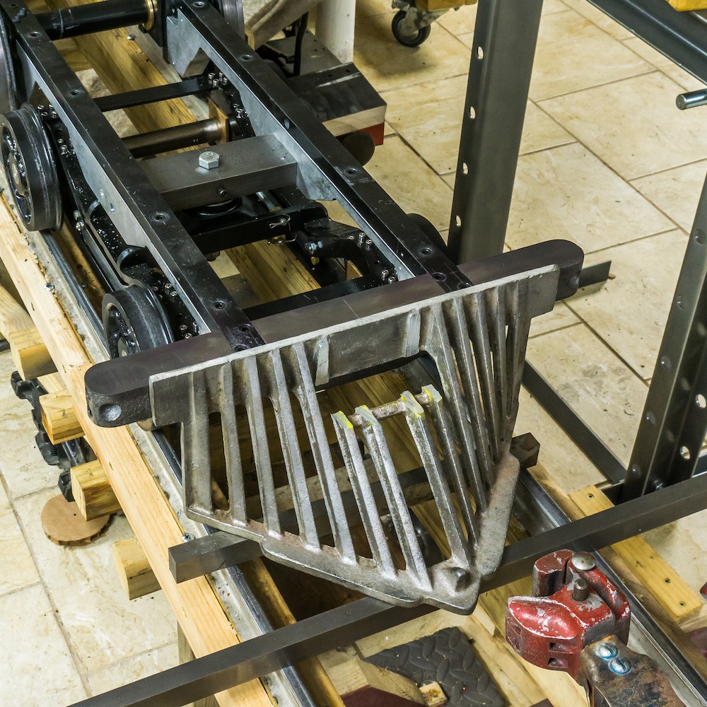
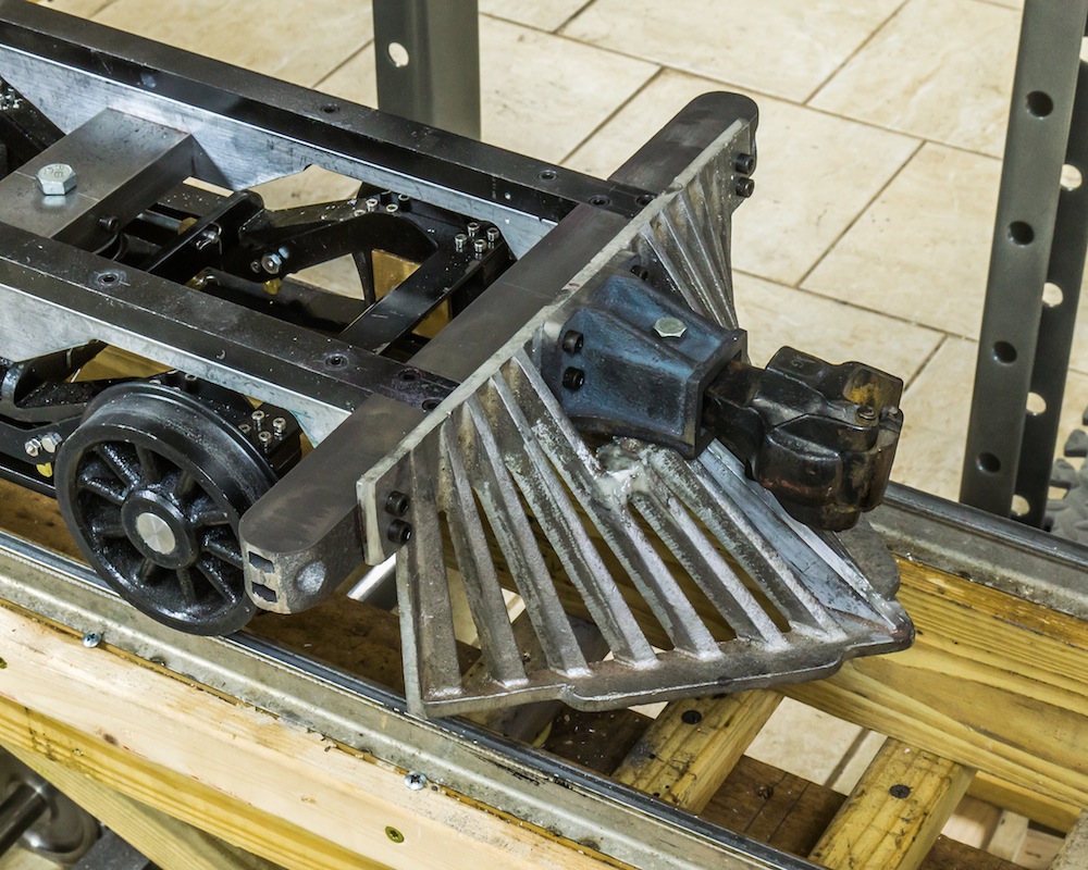
The “old-time” cowcatcher from Little Engines was cut out for the Allen Models coupler pocket. Compare this photo with the first photo. I milled off the protrusion in the front center and added a central rib. Two small pieces of aluminum were fitted to either side of the central five ribs for strength. All three pieces were screwed in with #2-56 screws and epoxied in place.
The cowcatcher clears the rails by 3/4 inch. The coupler and the hardware may be replaced in the future with a more realistic coupler and square headed bolts.