
The engine is a camelback, so the fireman’s space is located primarily on the front of the tender. Between several hundred train books I own and the internet, I could only find a small handful of photos illustrating the front of a tender. I do have photos of the side of the prototype, so the steps, grab irons and side gates are fairly accurate, but the doors to the coal bunker are partly from my imagination. The cast brass front steps are Reading caboose steps, but they were close enough to the CNJ steps and I had them in my collection of stuff.

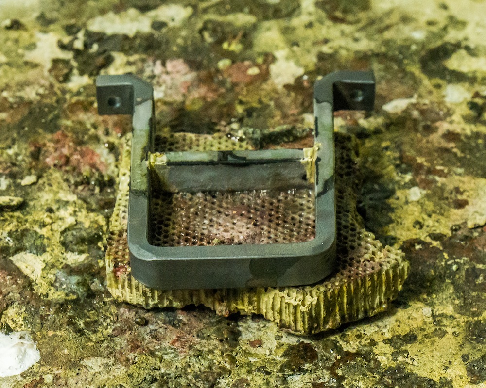
The rear steps are “stirrup” style and they were fabricated from 3/16″ x 3/8″ steel, with the rung silver brazed in place.


The corner grab irons are made from 3/16 inch diameter rod, which might be a little heavy, but the corners of the tender are likely to be abused over time, so robust details are better than lighter “true to scale” details.
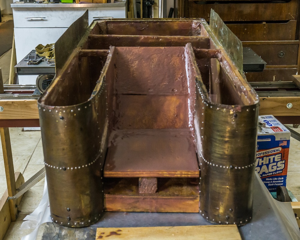
The first coal bunker I made was too small and not correct to the prototype tender. I was able to surgically remove the inside walls with an oscillating multi-tool and move them out to the sides.
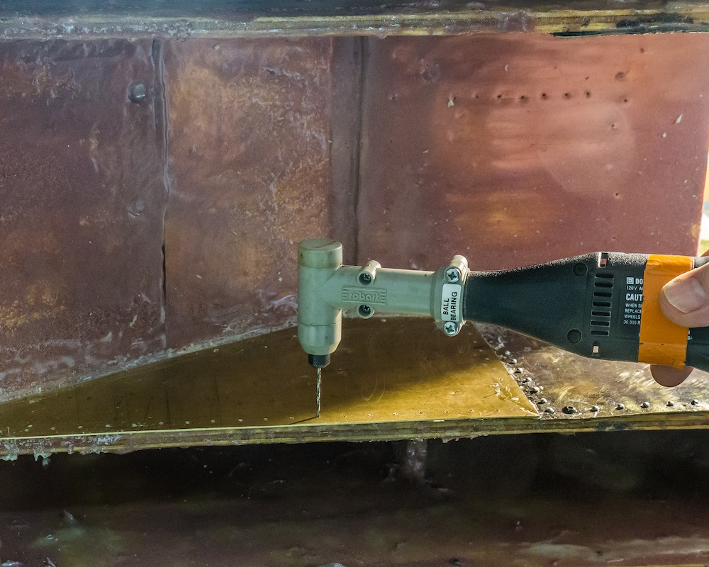
The right angle attachment for a Dremel tool is ideal for drilling out the rivet holes in tight spaces.

Once the side walls had been moved outward, the new coal bunker was made of 1/8 inch steel and scraps of brass sheet.

The coupler pocket is a casting from Allen Models. The rear ladder was constructed from steel bars and round brass rungs, silver brazed together and screwed onto the rear of the tank.

The fireman’s platform was made of steel sheet supported by brass angles.

The steps attached to the firing platform are fabricated from brass sheet. The gates feature operating hinges and locking mechanism (see top photo).

The doors to the bunker are fixed in place as shown. The plates on top of the forward water legs will eventually be drilled for valve handles. I will install the functional plumbing during the painting operation when the weather is warmer.

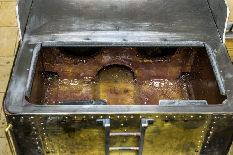
The inside of the tank has been coated with fiberglass and epoxy. It is not very attractive, but it only needs to be watertight!

The cast water hatch will allow the tank to be filled during operation. The larger plate the casting is attached to, lifts out for access to the interior of the tender. There are several small details to make and add – cut levers, poling pockets, ladder grabs,and miscellaneous hardware. I cannot do much more until the weather improves. When it does I will paint the parts I’ve made and finish the remaining details. The time has come to finish the chassis. I plan to steam the engine in 2022.
