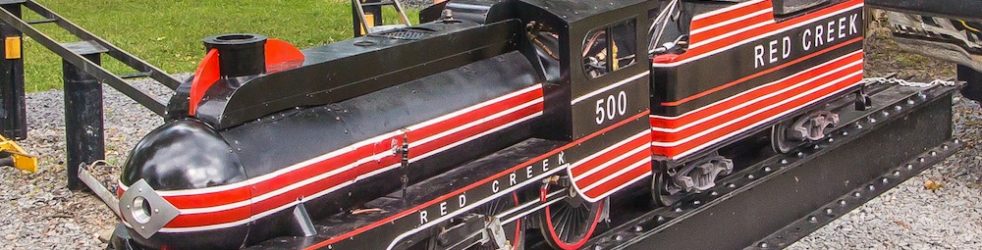
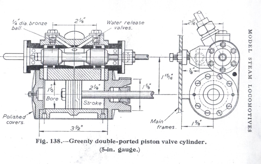
The locomotive I am building has outside pistons and inside valves. I have cast iron cylinders but I am constructing the piston valve housing from bronze tubes and copper fittings. Bronze liners will be pressed into the housing (black in the cross section above).

The housings are 5-3/16 inches long; the outside diameter on the ends is 1.65 inches; the outside diameter in the center is 1.56 inches; and the inside diameter is 1.27 inches.
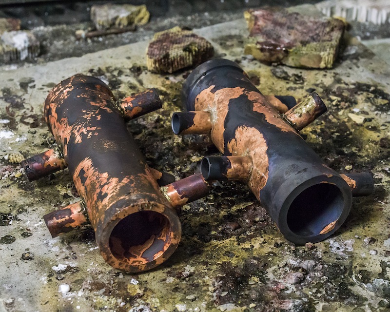
I silver brazed type K 3/8 copper tubing for the connections to the plumbing fittings. All the fittings were also silver brazed (45% silver).
I hydro tested the housing to find leaking joints. I did have to re-braze a few of the connections.

The water relief valves were cut at an angle in the housing, so I milled a flat before drilling the holes. Some of the fittings had to be “keyed” with a short piece of 1/16 inch diameter brass rod to keep them in position when brazing.
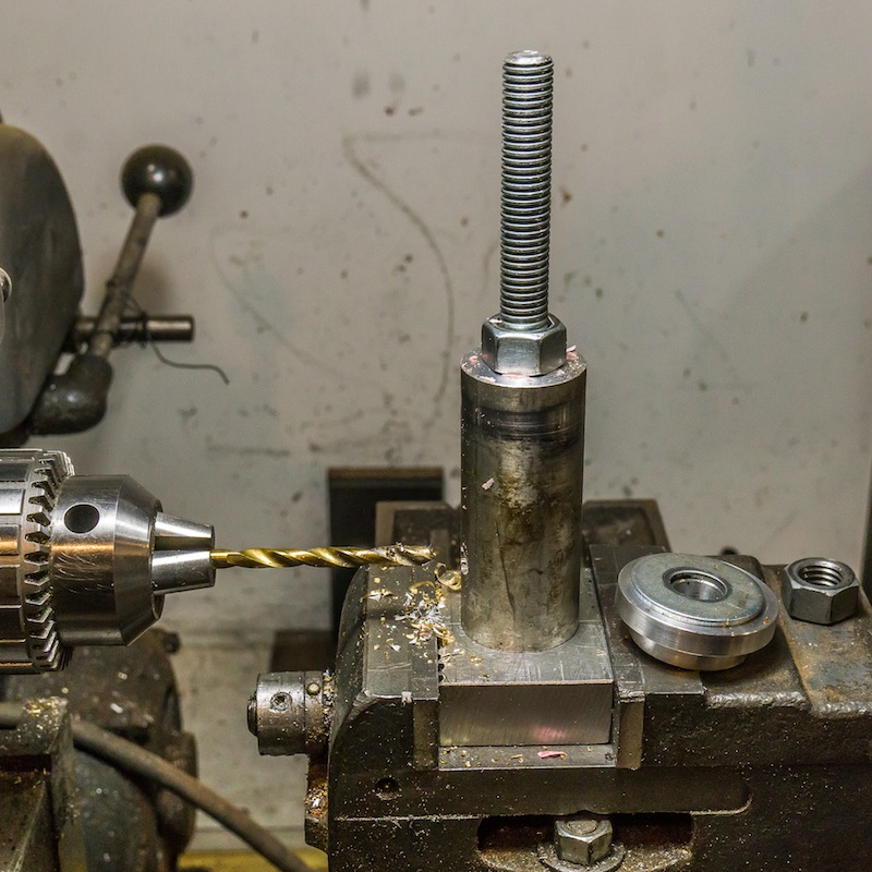
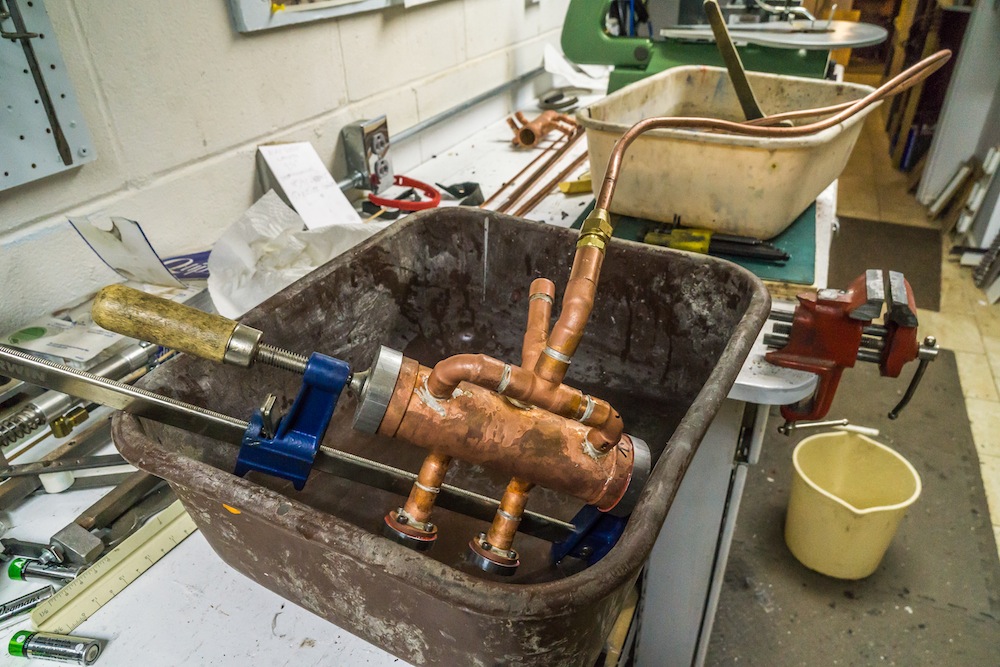
I made a simple aluminum fixture to hold the housings for milling and drilling.

I made two inserts (left in photo above) for each hosing. They needed to be accurately bored and honed for the piston valve. If a picture is worth a thousand words, then a model is worth a thousand pictures. I made a model insert from PVC and a piston valve from a wood dowel so I could better understand how the valve functions.
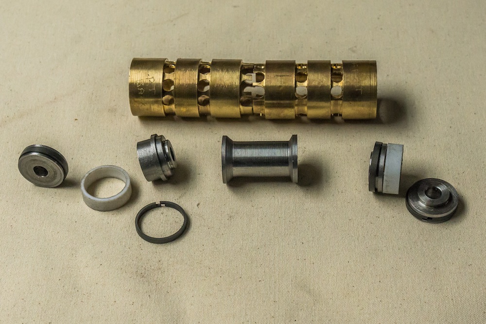
The photo above shows a pair of bronze inserts and the components for one piston. The piston is turned from 1144 stressproof steel. The iron piston rings will set the timing of the valve and the Teflon rings will keep the steam contained on the inside or the outside of the piston. The piston is hollow to allow exhaust steam to equalize on the outside ends of the piston.


There is a lot going on around the piston valves, so I am working on multiple components at the same time. The above photo shows a mock boiler and mock plywood saddle ends along with the real smokebox. I will need to drill the bottom of the smokebox to accommodate the stem entry pipes and the steam exhaust pipes. All of that has to be assembled and tested before I press in the inserts for the piston valves. The next task will be finishing and installing the smoke stack, so I can use it to line up the smokebox for drilling the bottom .
