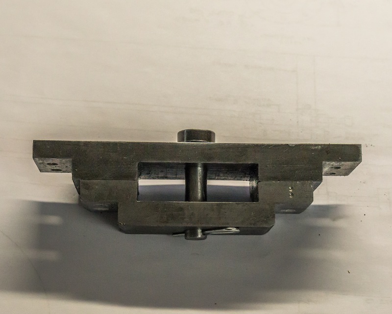
The mounting plate for the lead truck will be made next. It fits between the frame extensions.
I did not know what these parts were going to look like before I made them. I started with pieces of aluminum 3″ x 3/4″ x 18″. I cut and milled until it looked like it would function.
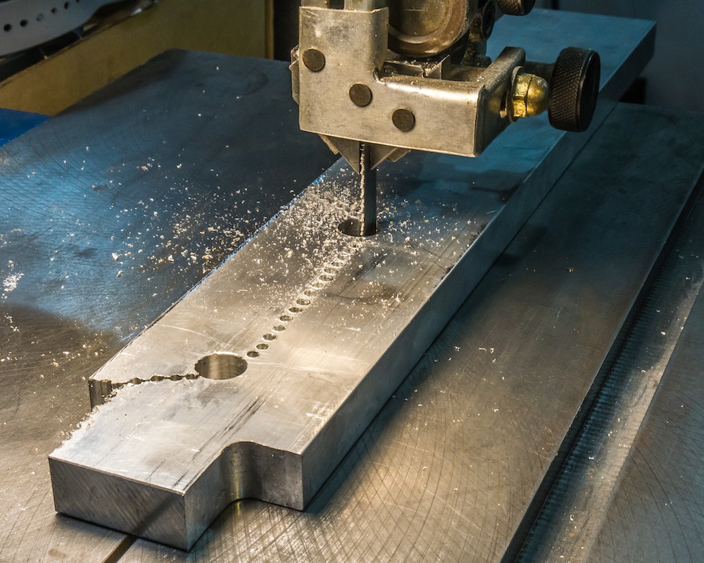
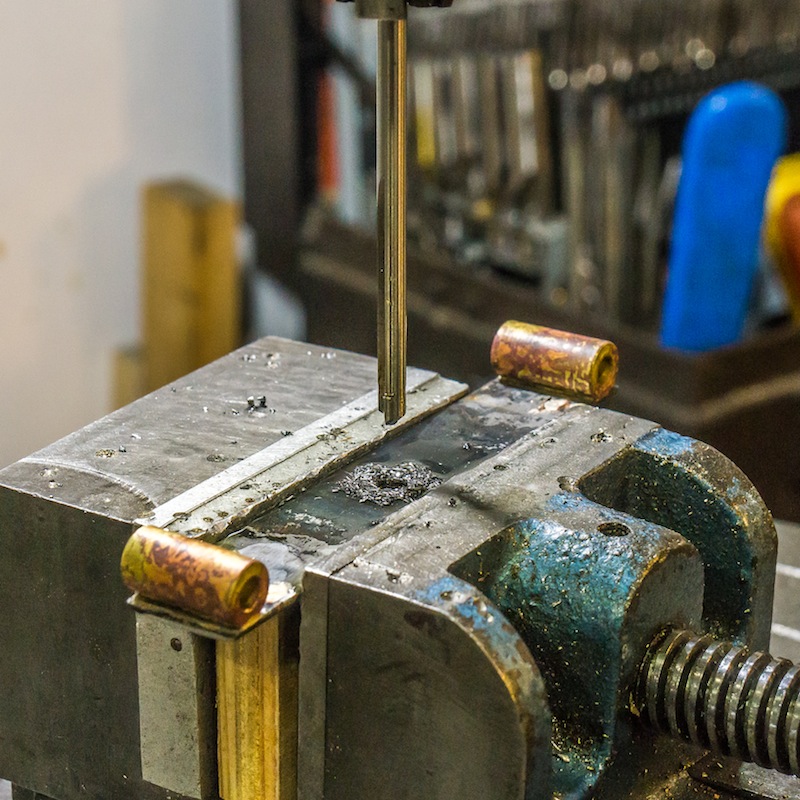
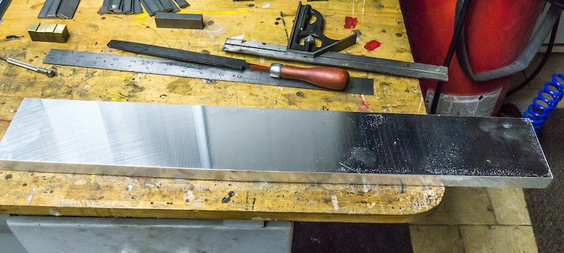
Sawing 3/4″ thick aluminum is very slow. I drilled a line of holes.
I then sawed along the holes.
Finally, I milled the rough line of half holes until the surface was smooth.
I have been using wood and plastic mock ups to design the front end of this engine, as I do not have any drawings – just some old photographs of the prototype.
This is a detail of a Central RR of New Jersey 4-8-0.
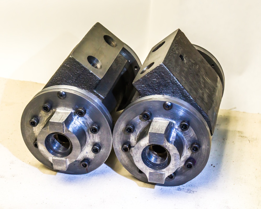
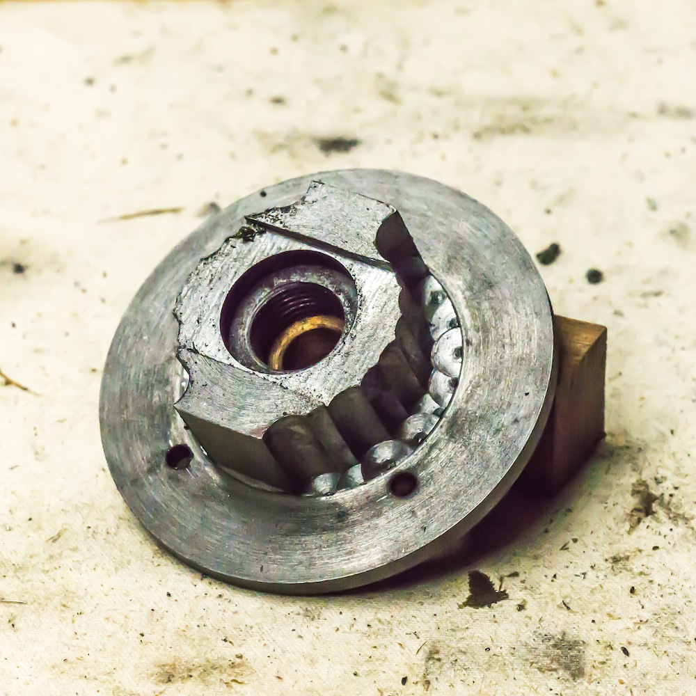
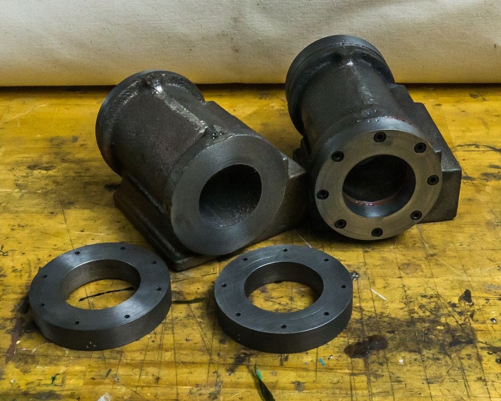
These heads were carved out of a 3-1/2 inch diameter cast iron bar. The ports will be attached to inside admission piston valves, inboard of the frame, controlled by Stephenson valve gear. They are angled at 50 degrees per the Brooks prototype.
The first operation was to turn the blanks on the lathe. The inside diameter is threaded 3/4-16 for the packing nut. A bearing was made from bronze for each head.
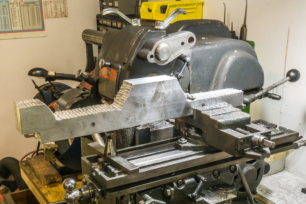
I used the above fixture to mill parallel flats, top and bottom and to rough out the profile between the flats by plunging with an end mill.
The roughed out profile is pretty ugly but it was a quick way to remove a lot of material.
I mounted a rotary table on an angle plate to finish mill the profiles between the flats where the crosshead guides will be attached. The last operation was drilling and tapping the mounting holes.
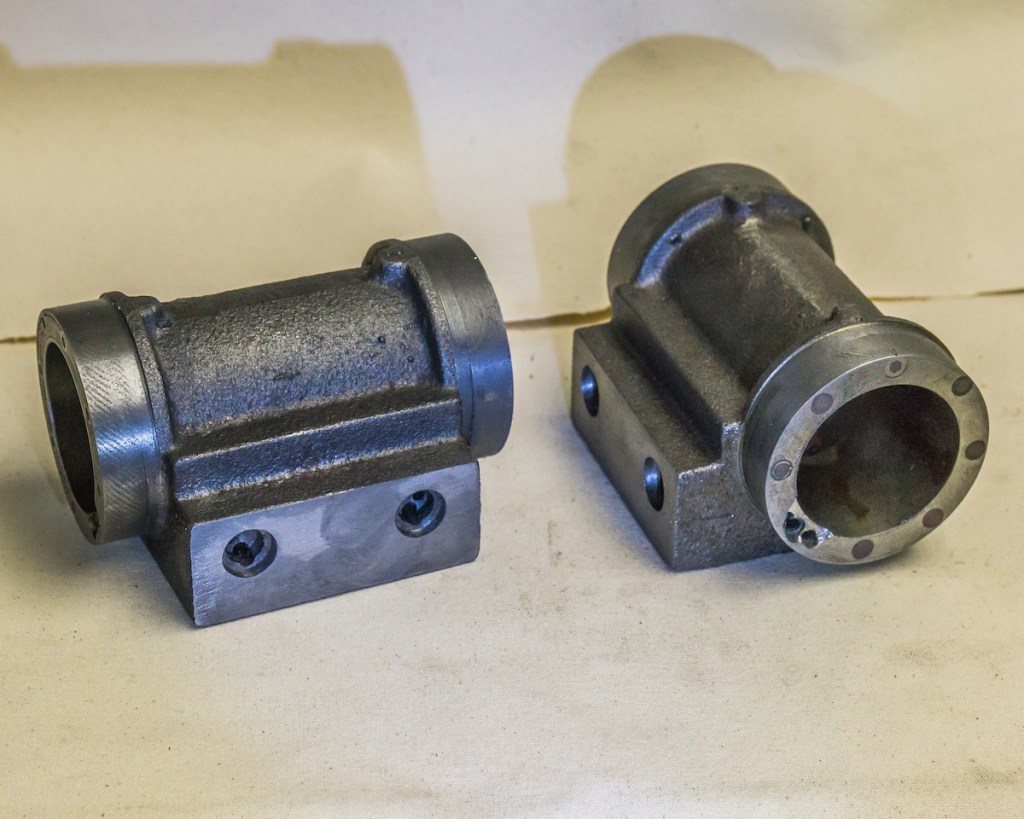
The prototype for this engine had extended piston rods on the front of the cylinder. I will use the boss shown on the left above as a mount for the extended piston rod cover (decoration only).
I made rings from 3-1/2 inch x 1/4 inch Cold Rolled Steel to fit over the ends of the cylinders because the steam ports were too close to the edge and I was afraid they would leak. The rings were pressed (approximately 0.002 inch press) on with Locktite No. 609.
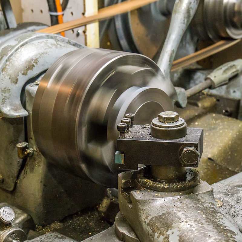
Turning the outside diameter of the rings (all four were bolted together for this operation).
Each ring was bored to size for the end of the cylinders. I made the aluminum spacer shown above, behind the ring mounted in the six jaw chuck.
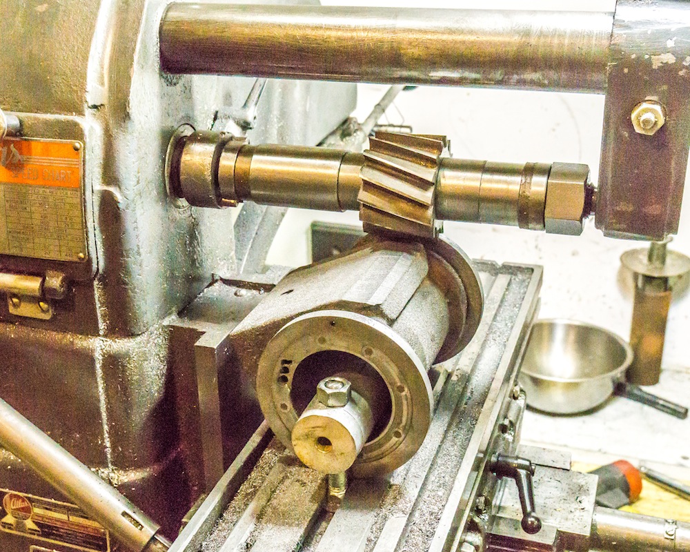
The photo above shows the setup I used to mill off excess material from the cylinder casting. I finished that section of the casting with an abrasive disc, so the material was slightly below the end rings.
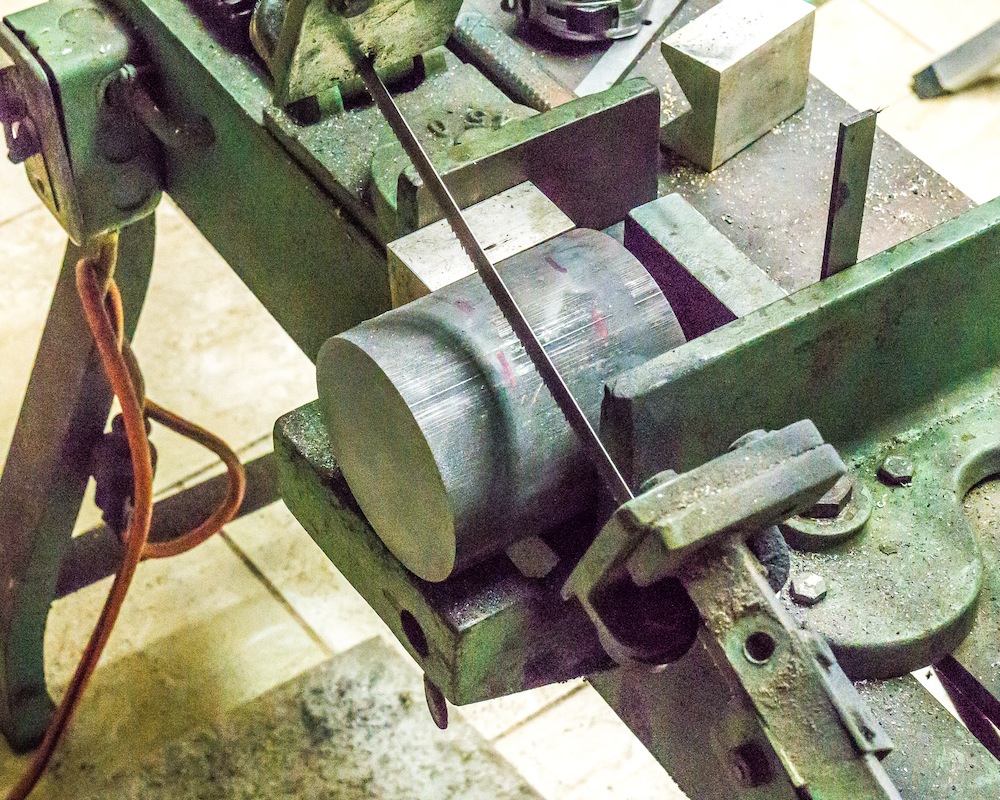
The cylinder heads were made from 3-1/2 inch diameter cast iron. It took about twenty minutes to slice through the bar. I needed four slices!
The cylinder heads were turned from the cast iron stock.
The cylinders have been bored to size (two inches in diameter) and the steam passages have been drilled and milled. Mounting holes for the end caps and valve connections will be match drilled when those parts are made.
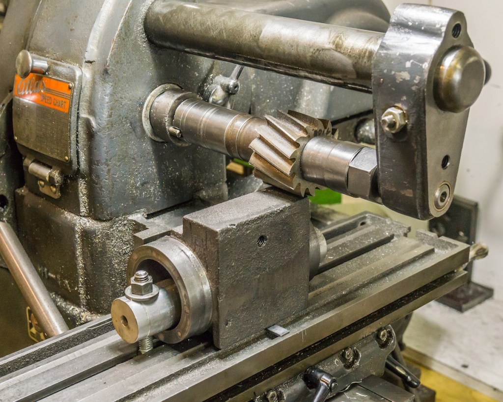
My first attempt at machining the cylinders was to mount them in a four jaw chuck. I was afraid there might be too much vibration on the outboard end and that proved to be correct. Two other problems became apparent with this setup. First, the 1/2 inch boring bar was not robust enough for a five inch bore. I could see it flexing as it got closer to the chuck. The second problem was alignment. I started boring at an angle. Fortunately I caught the problem before it was too late to correct.
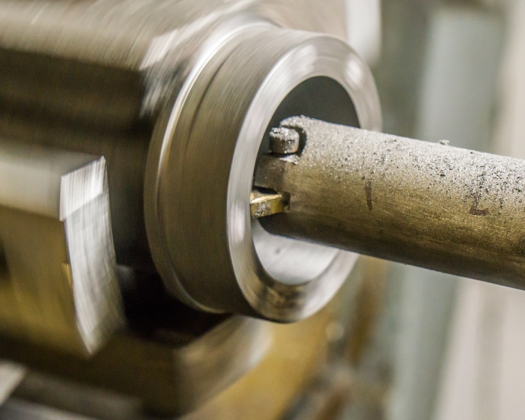
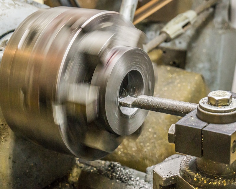
I made a new boring bar out of 1-1/8 inch diameter steel with a crbide insert mounted on the cutting end. I built a fixture on a face plate allowing more stability and accurate alignment. The aluminum plate was bored to a close fit with the end ring. Adjustment screws on the protruding blocks, allowed me to use an indicator on the outboard end ring for close alignment.
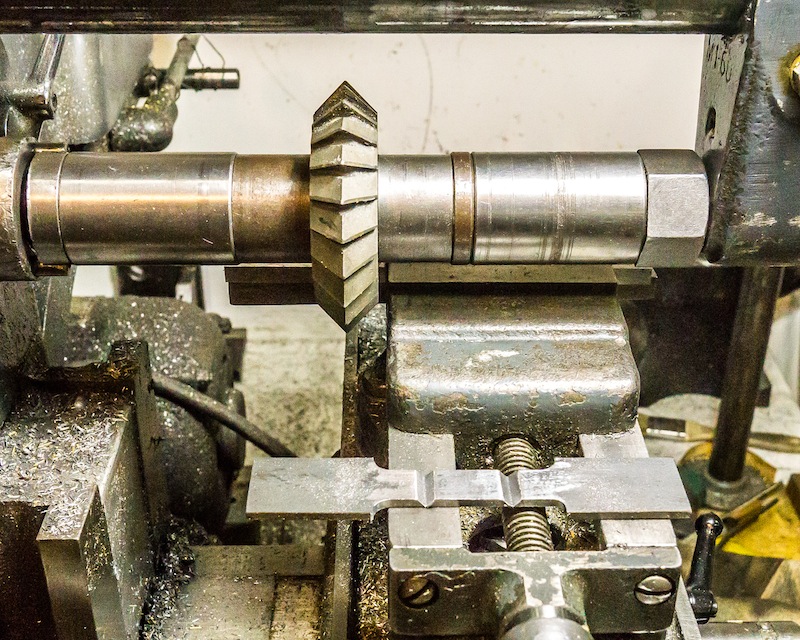
This closeup shows the insert starting a cut. I took off 0.020″ per pass for roughing at a fairly fast feed. Finishing passes were very small with a feed of 0.002″ per revolution.
The side of the cylinder where the connections to the piston valve will be made was milled flat and stoned for a smooth finish.
Three holes 3/16″ in diameter were cut in the end for steam passages. Three holes were cut at ninety degrees to intersect the end holes. Care was taken to not drill too deep. I measured the depth of cut often.
I used end mills to make a 5/8″ diameter counter bore to encompass the three side holes on each end of the cylinders for flange connections.
Finally, I milled a pocket over the end holes to allow steam to enter the end of the cylinder.
The stroke on this engine is four inches. I needed a little more length on the castings I’m using. I made four cast iron rings about 0.525 inches thick – one for each end of each cylinder.
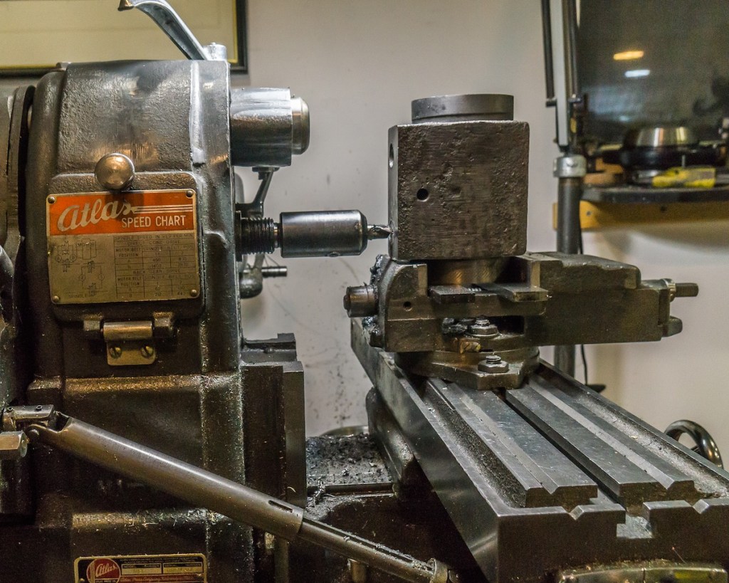
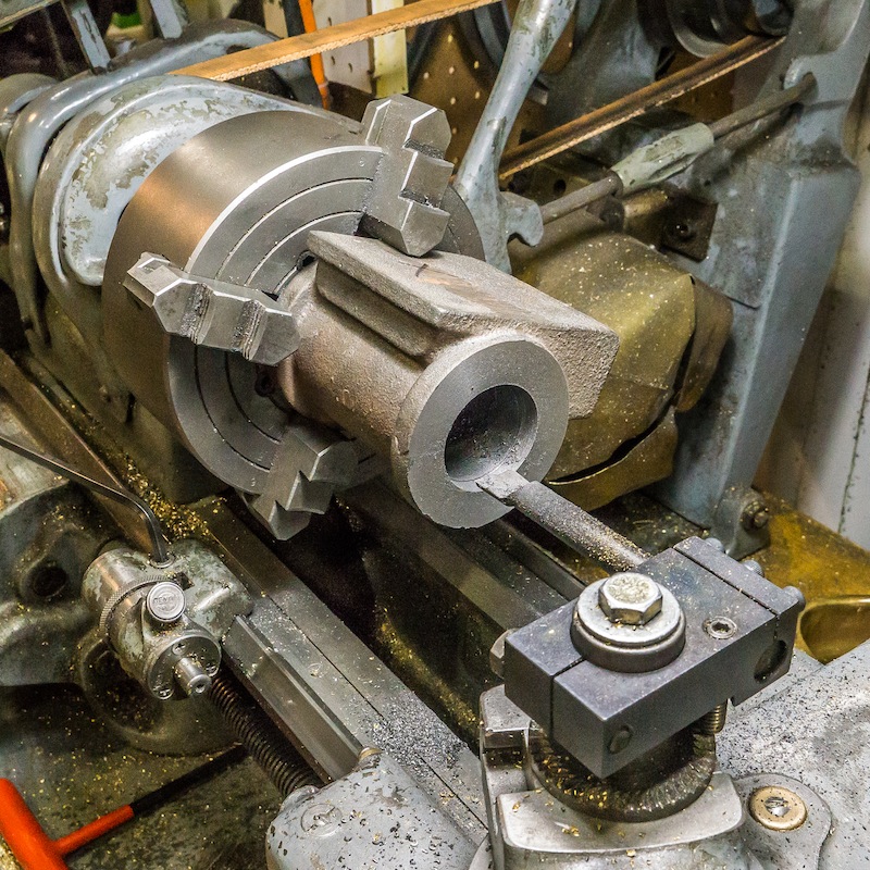
I mounted the casting in a four jaw chuck to face the ends and take a short rough cut on the bore.
The rings were sliced from a bar of cast iron. The first step was facing each side to length (thickness).
I drilled the disks to one inch inside diameter.
The I.D. was bored to the same rough diameter I had bored the cylinders.
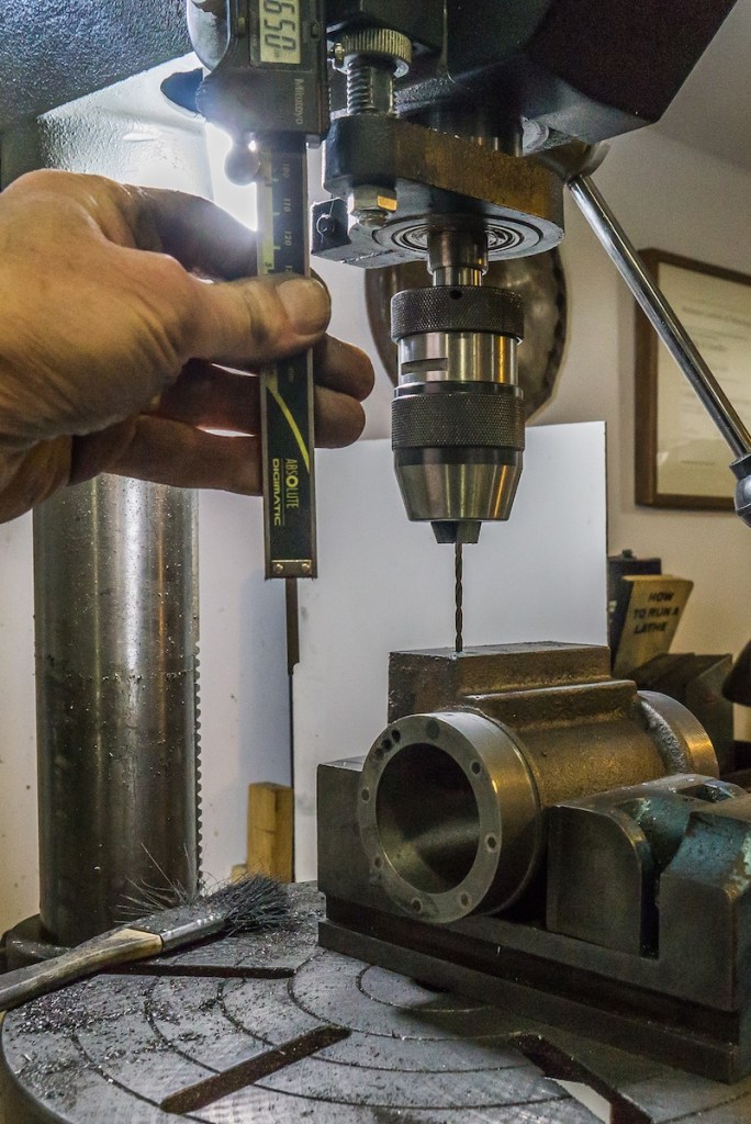
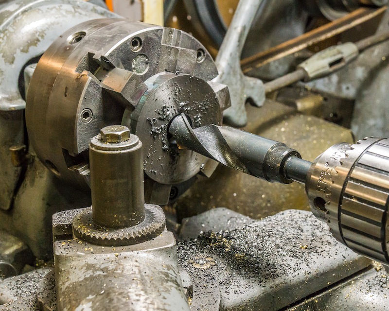
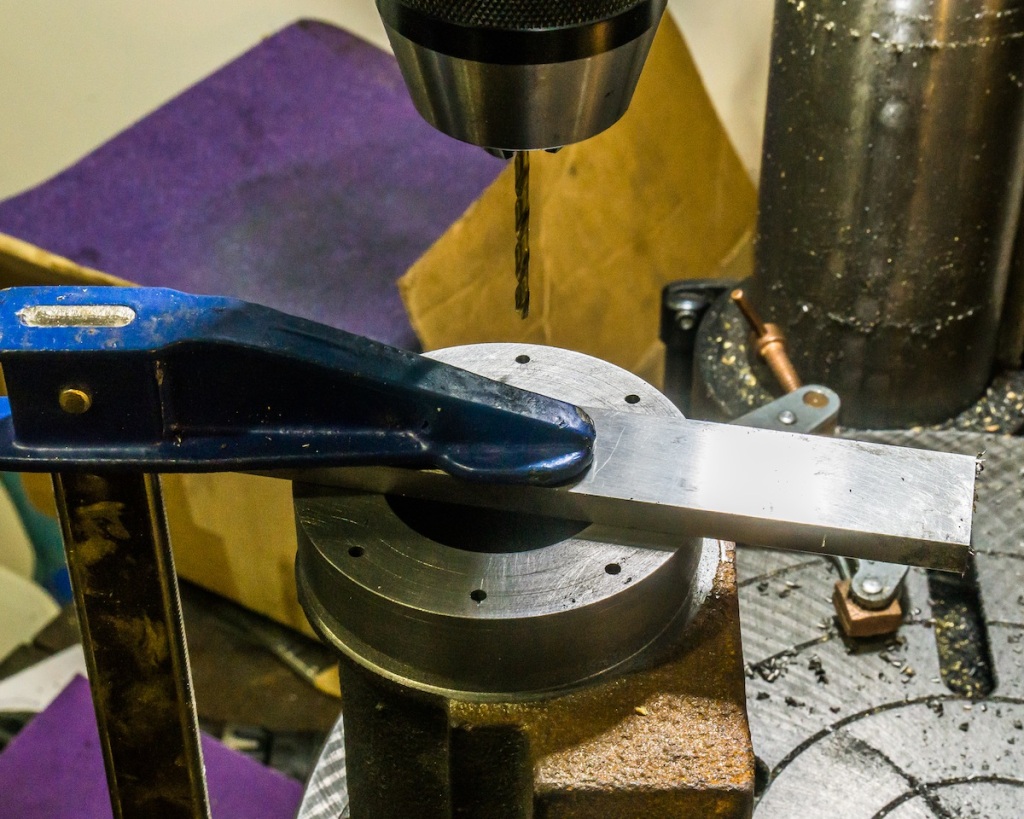
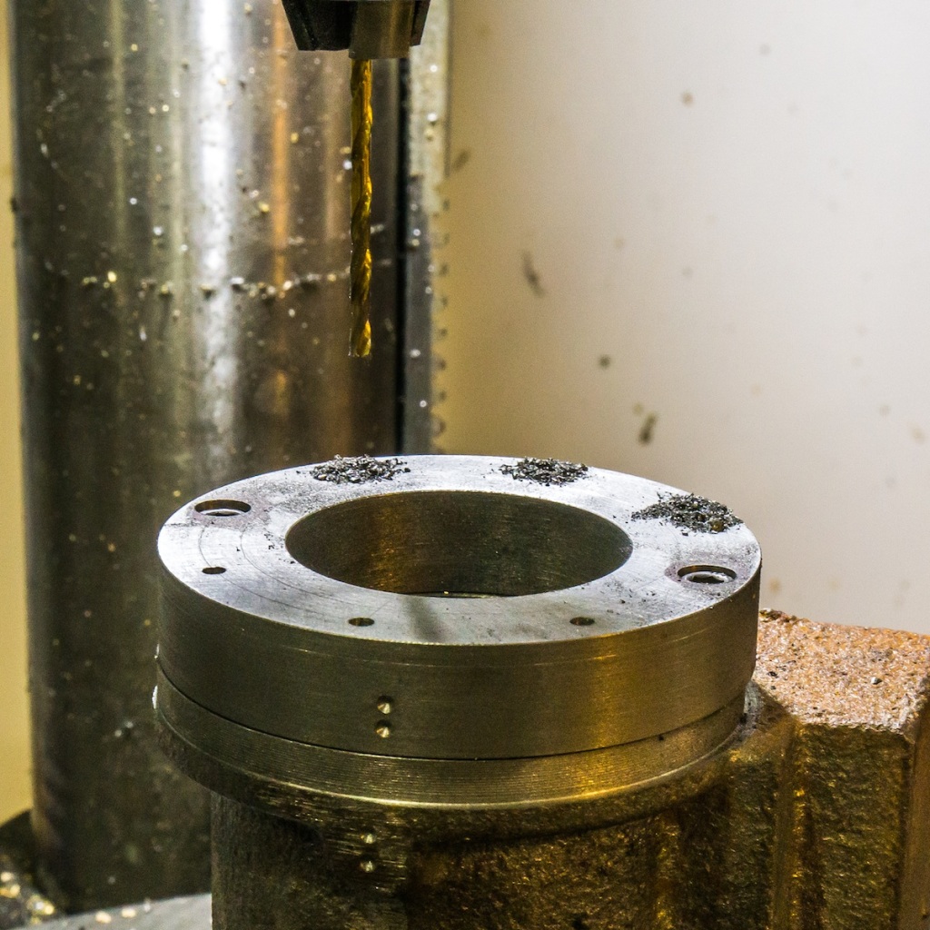
I drilled an eight hole bolt circle in each ring. I then match drilled the bolt circle to the cylinder ends. In the photo above, I am drilling two opposite holes into the end of the cylinder.
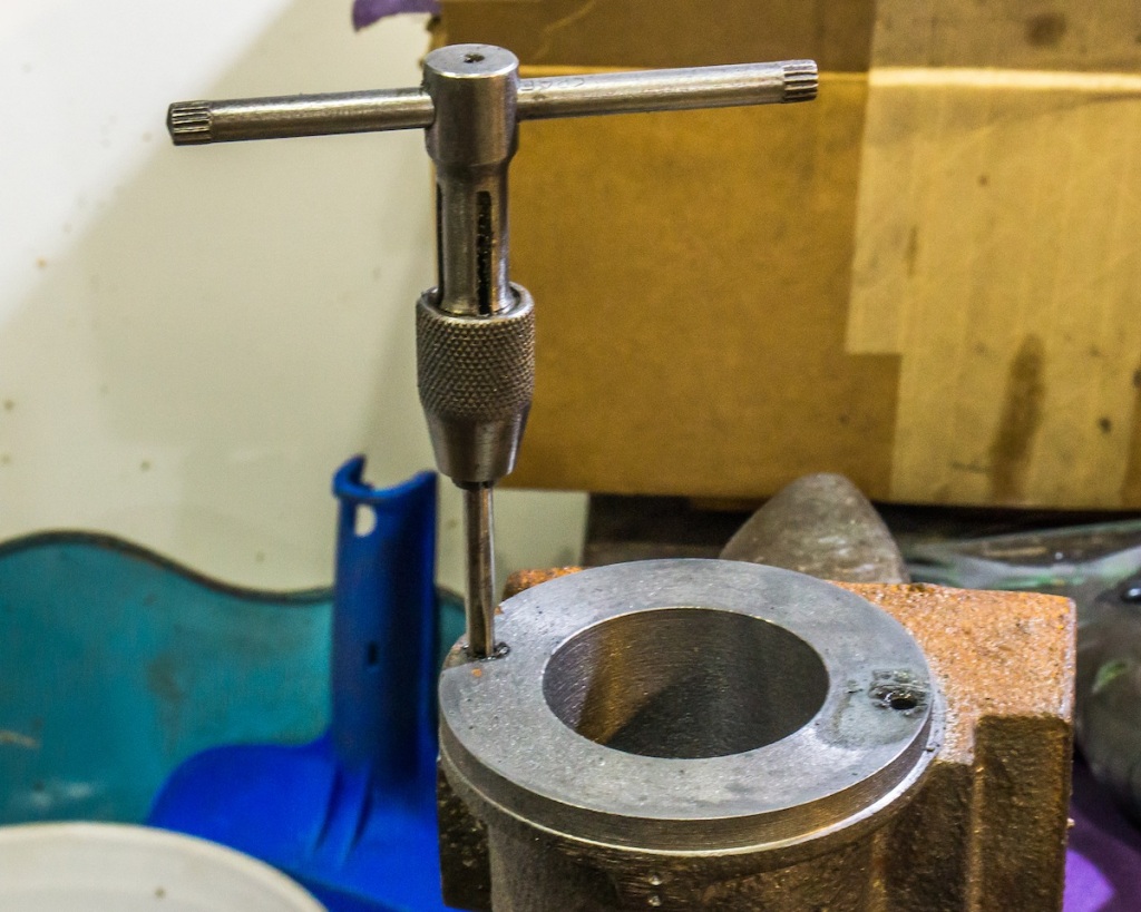
I tapped the two holes to no. 8-32.
I drilled a clearance hole and counter-bore on the two holes in the ring that correspond to the two tapped holes in the cylinder.
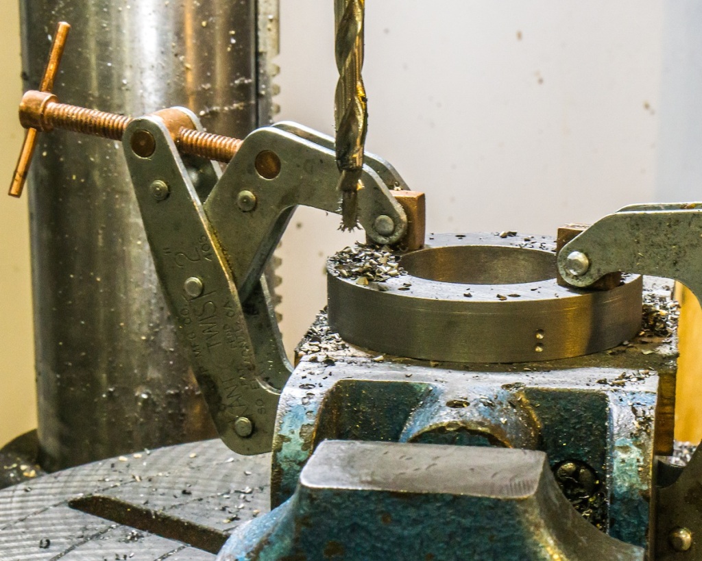
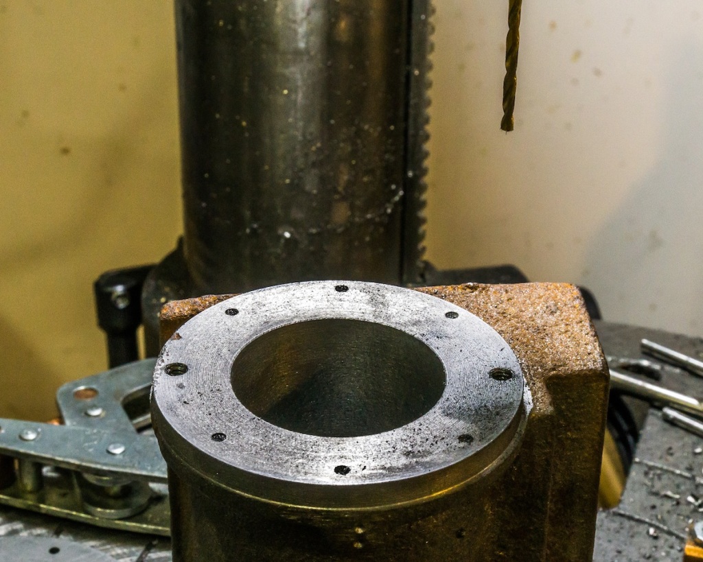
With the ring screwed to the cylinder, I match drilled the rest of the holes. Note the witness marks in the ring and the cylinder for aligning each ring to its corresponding cylinder end.
The bolt circle has now been transferred to the cylinder. The rest of the holes were tapped in the cylinders and the holes in the rings were opened up and counter-bored.
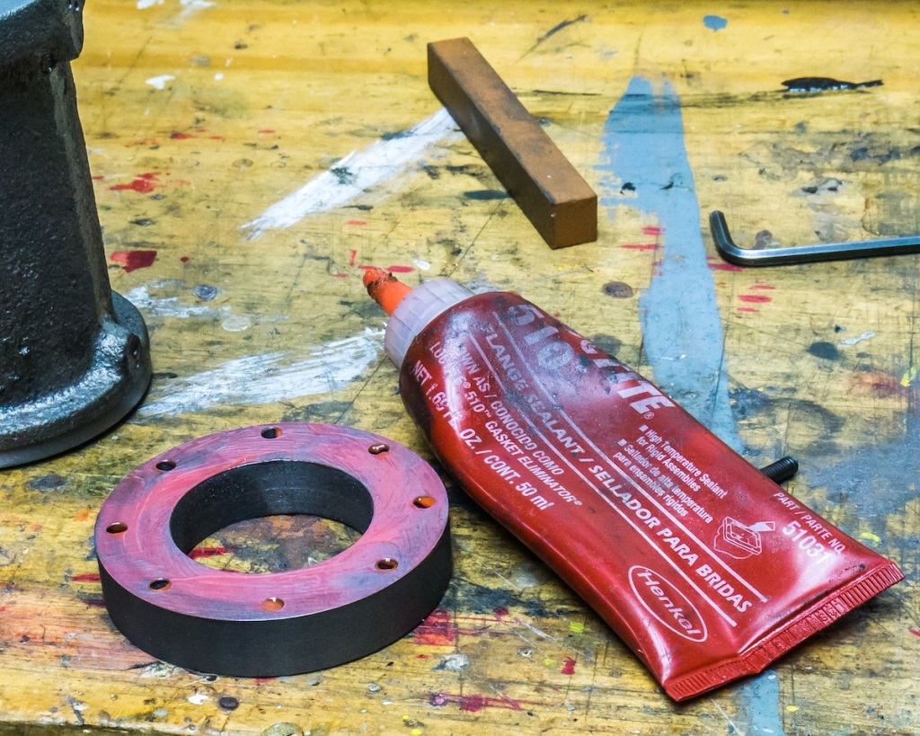
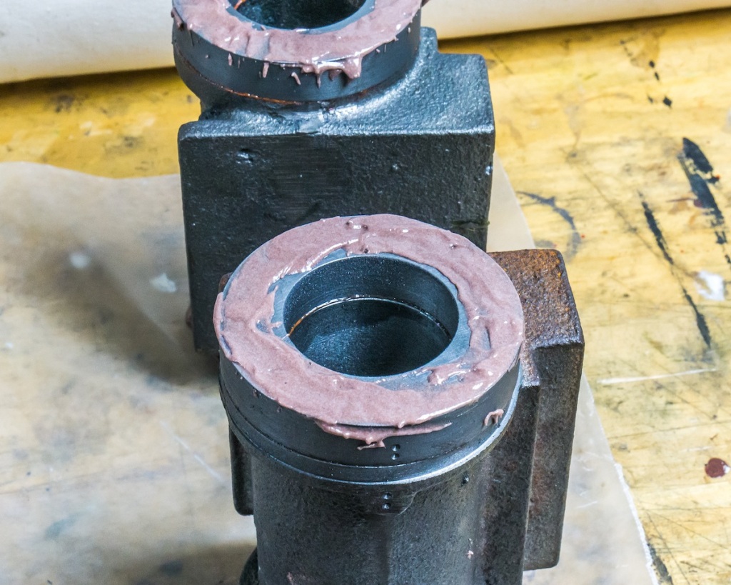
After lapping the rings and cylinder ends, one face was smeared with Loctite No. 510 Flange Sealant. The 8-32 socket head cap screws were installed with Loctite No. 263 thread sealant.
It may be overkill, but I filled the screw heads with epoxy to discourage anyone from ever removing these extensions. They will be bored and drilled with the cylinders as if they were one piece.
The Spring Rigging is the suspension on the eight drive wheels. I pretty much followed the Allen Models drawing for the consolidation. My frame members are 3/4 inch wide by 1/2 inch deep. Instead of using fake castings to represent the leaf springs, I made working leaf spring assemblies. I have two different sizes of spring material – 5/8 x 0.043 inch and 3/4 x 0.0625 inch. I purchased the material at a club auction a few years ago; which had been donated by Skip Enck who had used the material for the springs on his big D & H 2-8-0.
Spring steel is very hard and tough to work. I cut the pieces to length with an abrasive wheel in a Dremel tool.
I drilled the center holes in the spring leaves with a carbide tipped drill.
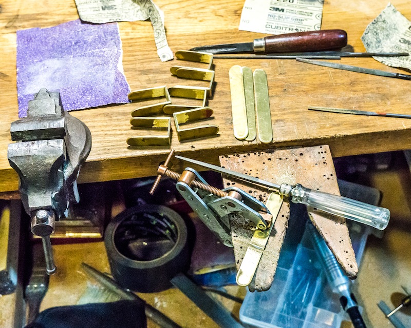
The leaf spring holders for the four rear drivers were made of brass. I filed grooves in the brass strips, folded them and silver brazed the corner joints.
The photo above is three of the rear spring assemblies. There are very complex calculations for making leaf springs. They are way too complex for me, so I made the base of each assembly out of the thicker material and used four pieces of the thinner material on top of each assembly. I tested the assembly by pressing down on the spring on top of a bathroom scale. As the spring flattened out the scale read 35 to 40 pounds. It is strictly a guess. They can be changed after I test run the engine if necessary.
There are six spring assemblies for the four rear drivers as shown above.
The front spring retainers are made of 1/8 inch thick by one inch steel. I milled the grooves in these pieces.
The steel pieces were folded to shape and the corners were silver brazed.
This photo shows the four spring assemblies for the front four drivers. I tapped the correct number of holes, but I somehow miscounted how many shoulder screws would be needed to assemble everything. I am three short.
I will paint all the parts and add the brake rigging and the cylinder mounts to the frame before I attempt a final assembly. I suspect it will be a challenge to put this all together with the wheels in place.
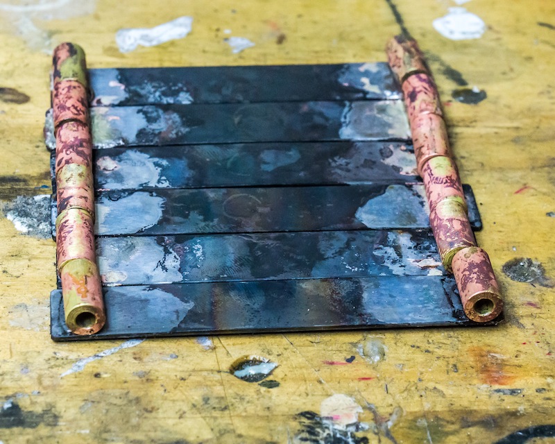
I had to silver braze the brass mounting hardware to the bottom leaf of each spring assembly. The photo above shows six leaves.
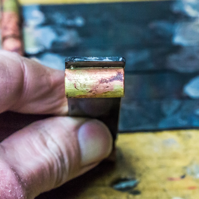
The photo above shows the silver brazed joint between the brass and the steel.
Soldering is a process in which two or more metal items are joined together by melting and putting a filler metal (solder) into the joint, the filler metal having a lower melting point than the adjoining metal.
Brazing is a type of soldering that uses a filler metal that melts at a temperature greater than 450 degrees C (842 degrees F).
Unfortunately, not everyone uses the term “brazing.” The model press (primarily British) and books dealing with jewelry making refer to brazing as “Hard Soldering” or “Silver Soldering.” “Soft Soldering” uses a filler metal that melts below 450 degrees Celsius. Soft soldering is used for plumbing and electronics.
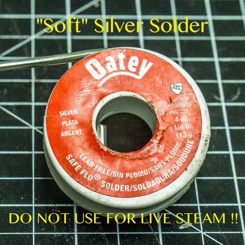
The term “Silver Soldering” has become confusing in recent years because plumbers have stopped using lead and many soft solders contain a very small percentage of silver – often less than 1%; but these soft solders are advertised as “Silver Solder!”
I know a live steamer who repaired a steam pipe on his engine using one of these soft silver solders. The package said “Silver Solder” and it was a really low price – what could go wrong? Well, as soon as he applied live steam to the repair it all fell apart! Now he had a bigger problem. If you do not remove ALL of the soft solder and you try to braze the part, the heat required to melt the brazing alloy will boil the soft solder and it will eat holes in the base metal like acid. He really should have known better.
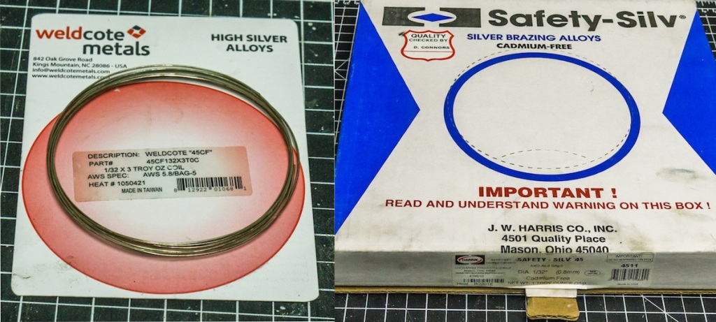
The photo above illustrates two brands of 45% silver brazing alloy. I buy the cadmium free alloy – it is less poisonous. I use 45% silver for most brazing applications. Alloys are available with different percentages of silver. The higher the silver content, the higher the temperature required to melt it.
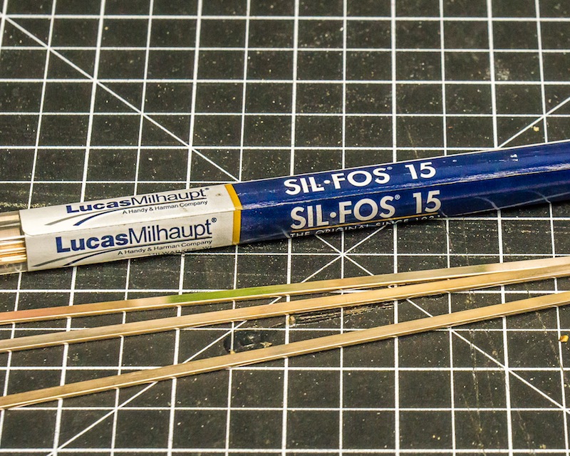
Phos-copper is a popular brazing alloy. The photo above shows 15% silver.
This photo illustrates “SOFT” silver solder. Do not use it for live steam or where you need mechanical strength in a joint that could be subjected to outside forces.
There are two different techniques used to braze metals together. Which one you are familiar with depends on whether you were taught by a welder or a silversmith/jeweler.
If you were taught by a welder, you mechanically clean the joint (scraper, file, abrasive, etc.), apply flux to the joint, heat the joint with a torch and push a rod or wire of alloy into the joint similar to using a welding rod. This process is fairly quick, but it wastes brazing alloy and leaves more melted alloy on the parts than is needed to join the pieces together. This is usually not a problem for industrial parts.
If you are a silversmith or a jeweler, you will be concerned about excess brazing alloy because it is a different color than the base metal. High cost is another consideration (Yes, they make gold and platinum brazing alloys!).
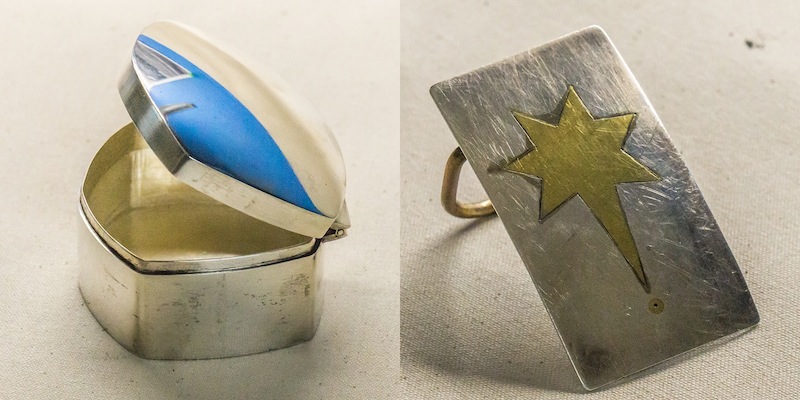
The photo above is a sterling silver box and a brass and silver belt buckle I made many years ago. The box shows at least five joints, but they are not easily visible because there is no excess alloy outside the joint. The belt buckle however, illustrates excess alloy. It is the gray material between the brass and the silver. It is hard to see when highly polished but as soon as it starts to oxidize, the color difference is very apparent.
Jewelers clean and flux the metal, and heat the parts until the flux melts and gets “sticky.” Very small pieces of brazing alloy are then applied to the joint with tweezers. The entire piece is heated until the alloy flows into the joint. A sharpened steel skewer can be used to push the molten alloy along the joint. Excess alloy can be filed or sanded off if the part is decorative.
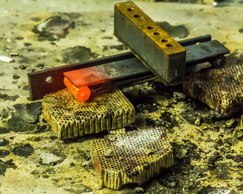
I made a steel fixture to hold the parts in position while I brazed one end at a time. You can keep brazing alloy away from an area by making that area “dirty.” Grated rouge and alcohol can be used to make the metal dirty.
The Allen Models castings for this part would not work on my model because the rear end of the firebox on a camelback is very close to the end of the frame with the rear wheel not far away. The Allen castings are too long.
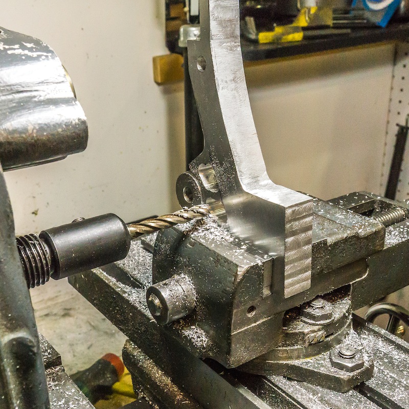
I thought I would make the parts out of aluminum bar stock, but when I arrived at my local metal supplier yesterday, he had a pile of jig plate cutoffs in his scrap bin. He sells this material by weight regardless of quality or size, so I scored a nice piece of MIC 6 jig plate (3/4 x 4 x 24) for $25!
Aluminum jig plate
The first thing I did was layout an outline of the parts and cut rectangles out of the larger piece.
I drilled 3/4 inch holes for the inside corner radii and then rough cut the parts on the band saw.
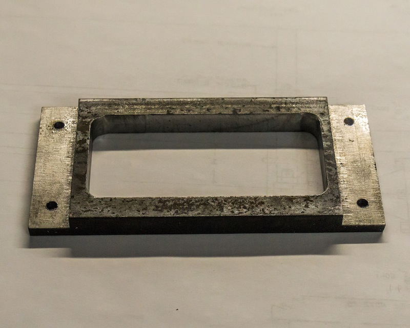
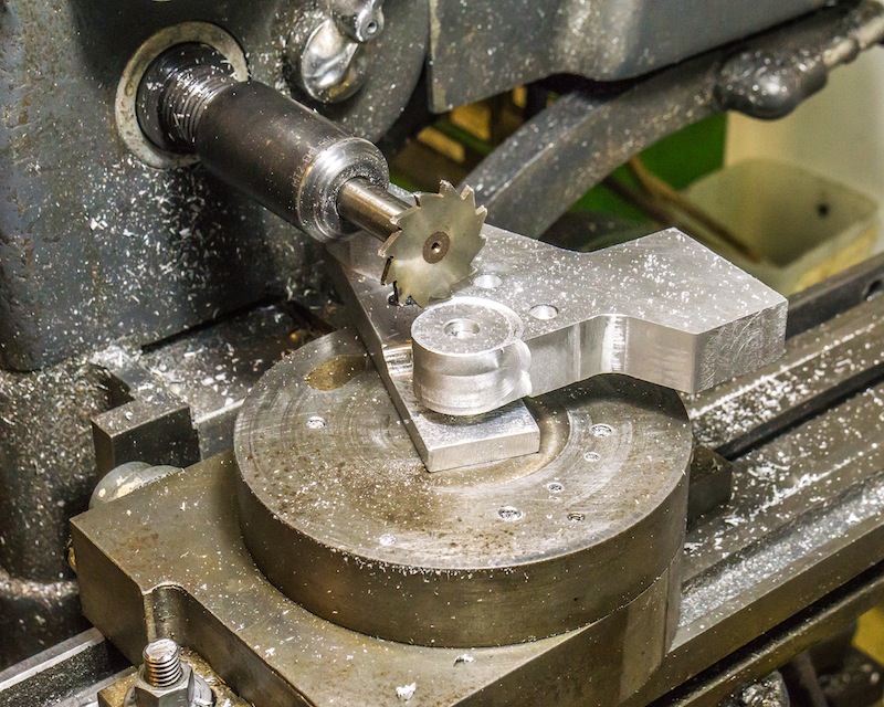
I cleaned up the edges with an end mill, files, and a belt sander, with the two parts screwed together. The outside radius where the brakes are attached was milled using a rotary table. I used the odd mill shown above to mill a groove detail on the surface of the part.
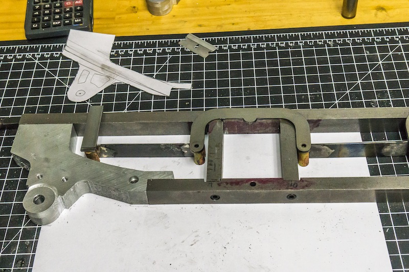
I placed some of the spring rigging parts on location to test fit inside clearance.
Finally, I did a little freehand end mill carving to make the parts look more like a casting and less like jig plate. These parts will be painted black and mostly hidden by the rear driver and brake parts.
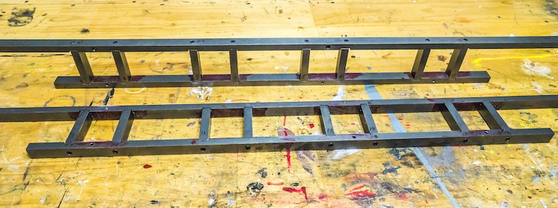
The basic frame members are 1/2 x 3/4 inch cold rolled steel, fastened together with No. 10-32 socket head cap screws. I will be spending several weeks making parts for: the spring rigging; the brake rigging; valve gear supports; cross bars; and other parts to finish the chassis.
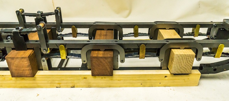
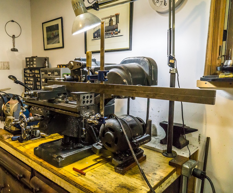
I had to rotate my milling machine 90 degrees so the long frame parts would not hit the wall. Left and right members were screwed together. so the slots would be in the same position on each side of the frame. Unfortunately, I could not accurately machine the slot locations. I laid the locations out with scribed lines and eyeballed the location of the milling cutter for each slot. In some cases I had to go back and make the slots a little wider to make the assembly work. I made the side rods first because I could machine those parts accurately.
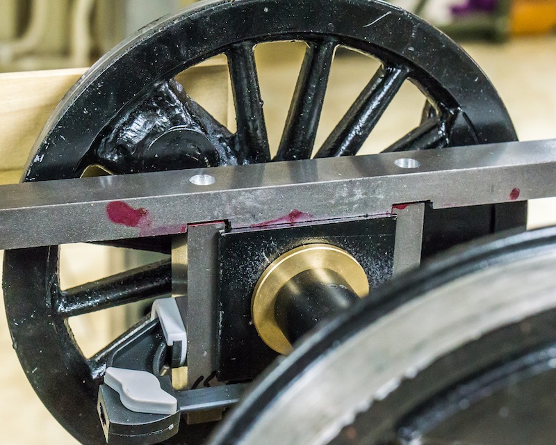
I put the wheels in their proper positions by temporarily attaching the side rods. I then clamped the side pieces against the bearing blocks (a .010 thick brass shim was inserted between the bearing block and the side piece, on both sides). I located the position of the hole to be tapped in the side pieces from the previously drilled holes in the top frame member. After a test fit of the top and side pieces on the bearing blocks, I attached the bottom frame member. I suspect it is going to be loads of fun assembling the whole mess when the rest of the parts are attached to the frame!