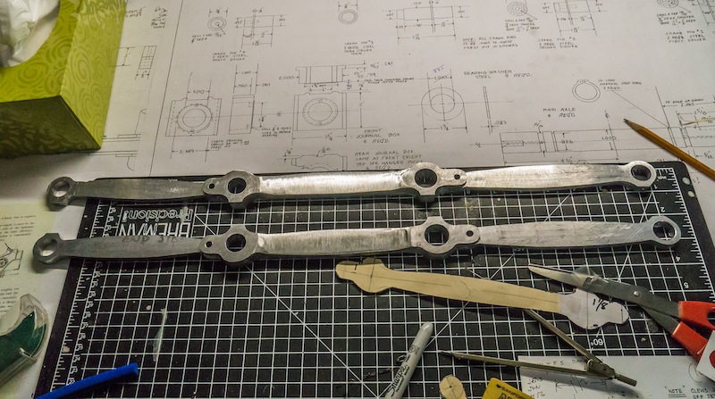
I sure wish I had a CNC mill when I made these parts! Alas, I had to carve them out of 6061 T6 aluminum bar stock using my horizontal mill, band saw and belt sander.
Bars of aluminum were cut to length and right and left pairs were screwed together. The crank pin holes were drilled and reamed to size.
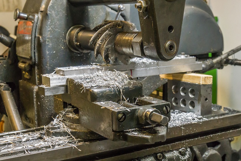
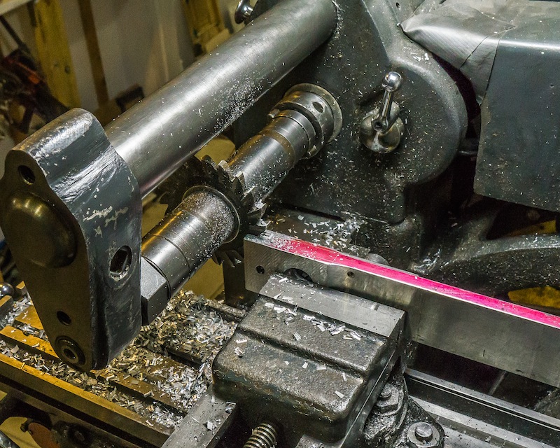
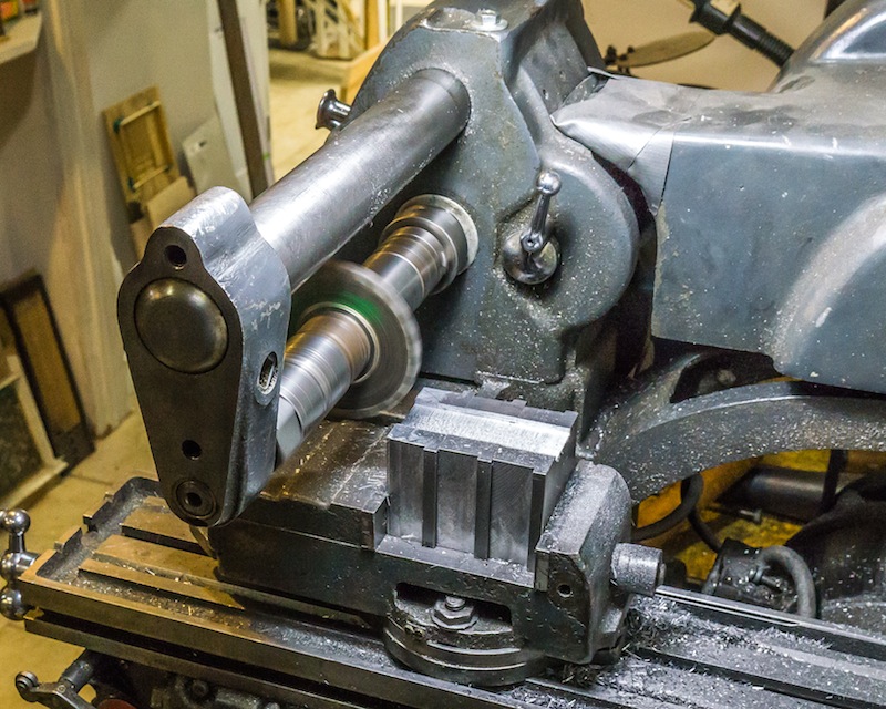
I was able to use a wide milling cutter to adjust the thickness of the bars.
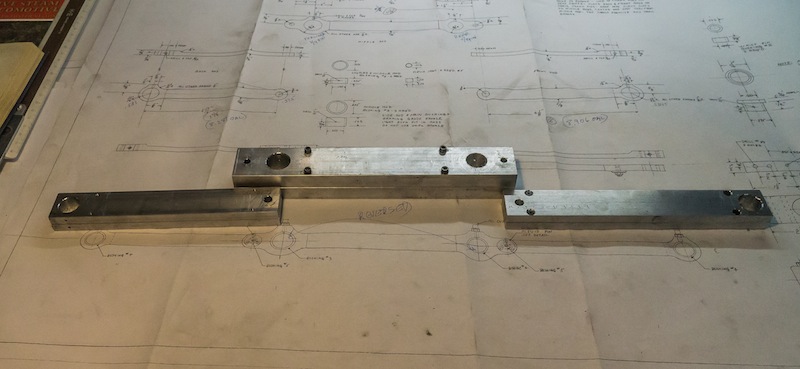
One of the rods after milling the thickness.
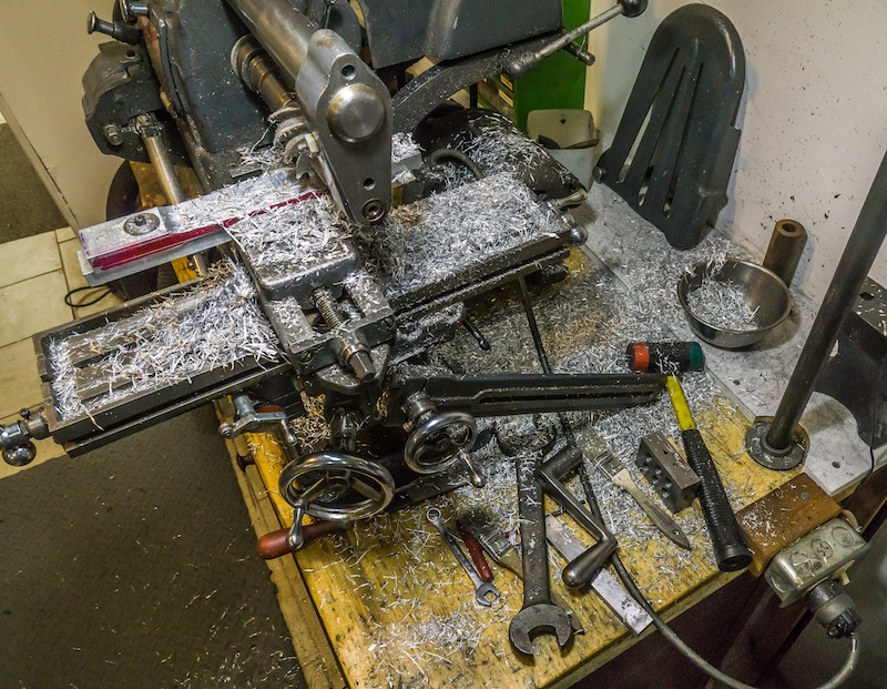
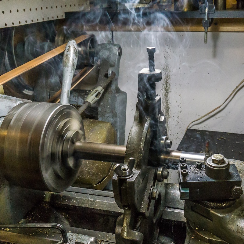
This operation made a hell of a mess! There were aluminum chips everywhere in my shop.
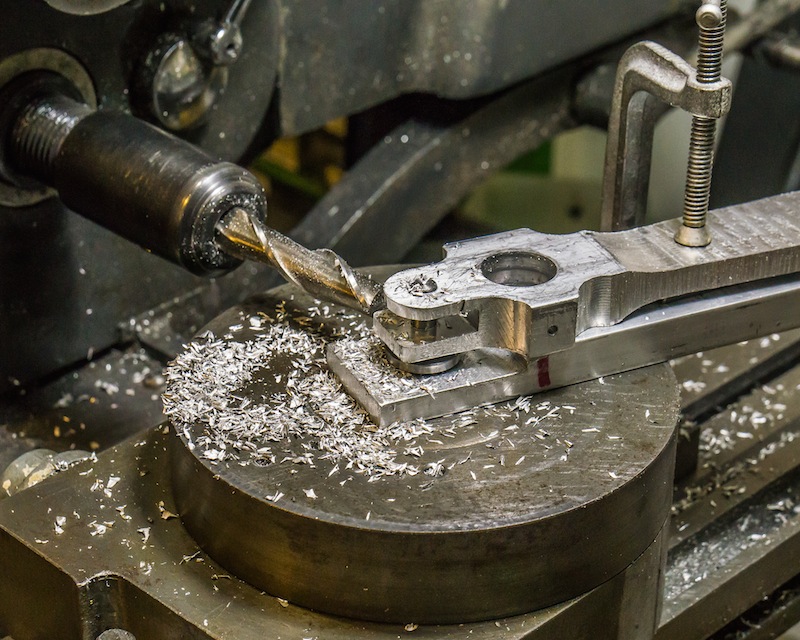
Milling the end slot of the middle rod.
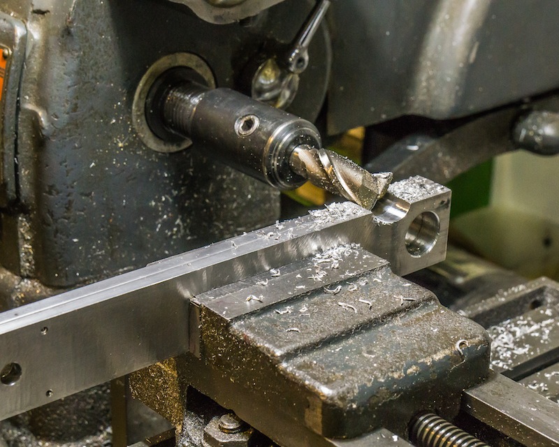
Inside radii were made with a 3/4 inch end mill.
The outside profile was roughed in on the band saw.
The ends of the rods were milled using a rotary table.
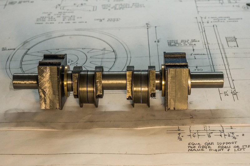
The parts were finished using a one inch wide belt sander. The bearings were turned from bronze stock.
I mentioned earlier in this blog reasons why it is a good idea to design and manufacture equipment that will accommodate both 7-1/4 and 7-1/2 inch gauges.
I am making the frames narrow enough for 7-1/4″ gauge; and the cylinder spacing wide enough for 7-1/2″ gauge. I made 1/4″ wide split bushings for the axles and the cranks.
7-1/4 inch gauge (rear) and 7-1/2 inch gauge (front)7-1/4 inch gauge (left) and 7-1/2 inch gauge (right)
The bushings I made are split all the way through so they can be taken off the engine and re-positioned after the wheel has moved in or out.
Will this work? I hope so…I guess I will find out…
Will it be easy? Probably not. I imagine after the gauge has been in one position for a few years, it will be a pain to change the gauge, but a little cursing is a whole lot easier than major surgery!
The procedure for making the bushings is:
Turn the O.D., I.D., and thickness to size.
Mill corners for the screw heads.
Center drill and tap drill two holes parallel to each other on either side of the center bore.
Slice the bushing in half perpendicular to the drilled holes.
Tap the bottom half of the bushing.
Clearance drill the top half of the bushing.
On the axle bushings, broach a keyway slot perpendicular to the cut half.
Material dimensions:
Axles and main crank: 1.5″ O.D. x 0.75″ I.D. x 0.25 thick. Socket head cap screws are No. 6-32 x 5/8″.
Three cranks: 1.188″ O.D. x 0.625″ I.D. x 0.25″ thick. Socket head cap screws are No. 5-40 x 3/8″.
I used brass and I made extras while I had everything set up.
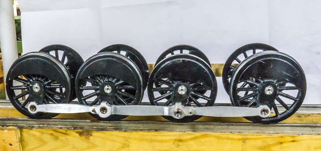
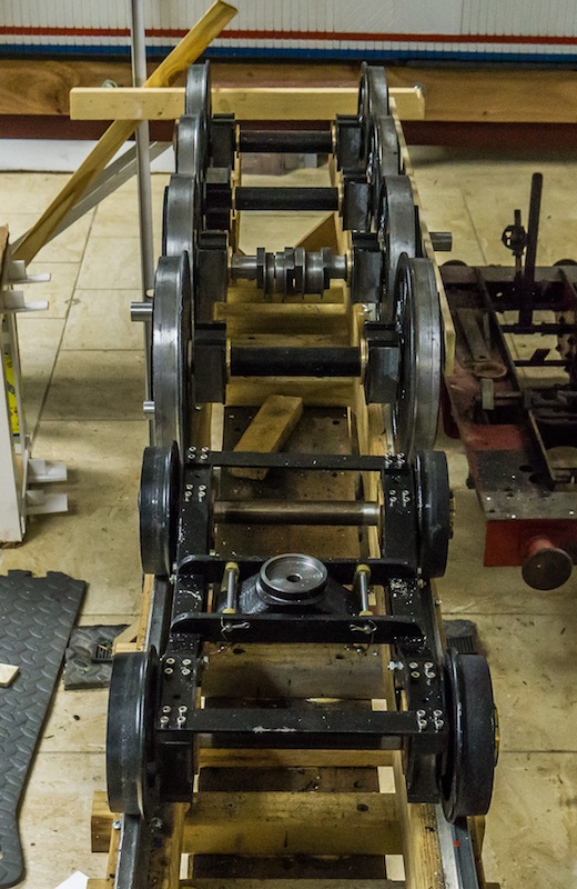
The photo shows the finished lead truck and all 8 drive wheels.
The axles were pressed into the right hand drive wheels with a .002/.003 interference fit (don’t forget to slide the bearings on first). The left hand wheels are a close slip fit to allow the gauge to be changed from 7-1/4 to 7-1/2 inches.
The left side of the engine is on the right side in this view.
My intention was to make the drivers a right hand lead, but when I got the wheel sets assembled, I realized they were left hand leading. The critical back to back dimension, while in specification on the axles is slightly oversize at the flange on two of the wheel sets. I will trim a small amount from the left side of the axle to adjust this dimension.
There are many different methods for quartering drive wheels on a model locomotive. I chose to put the keyway slot in the same place on each wheel and quarter the axles.
I milled the keyway in the first end, holding the axle in a vise.
Putting the slot in the opposite end of the axle requires a fixture to set the angle between the two slots at 90 degrees and ensure all the axles are exactly the same.
The angle plate I made had a broached hole opposite the center, holding the front of the axle. A key inserted in the first axle slot ensured repeatability on all of the axles.
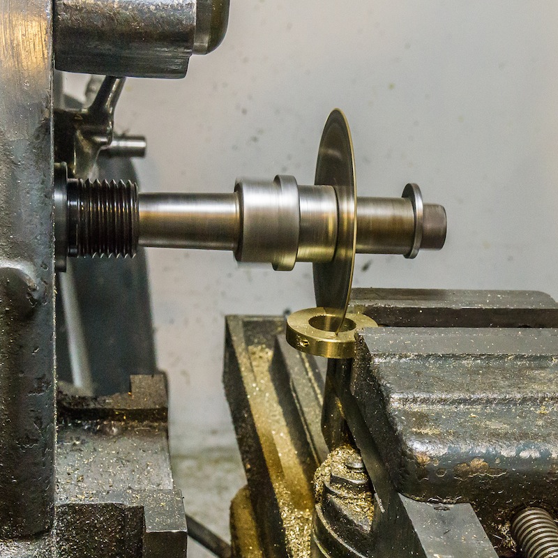
I machined the four main axles out of one inch diameter 1144 (stress proof) steel. The right hand side will be pressed onto the wheels with an interference fit. The left hand side is 1/4 inch longer than the right side to accommodate changing gauge (7-1/4 and 7-1/2).
The axle stock is mounted in the lathe with the steady rest near the end. I used an indicator to adjust the runout on the end of the axle to a couple of thou.
I machined the ends to fit the wheels and bearings. Put unique witness marks on all mating parts, to make assembly easier after painting.
The “back to back” dimension on the wheel sets is critical to their function. I set that dimension for 7-1/4 inch gauge. A split spacer will be added behind the wheel to make the wider 7-1/2 inch gauge.
The axles are now ready to cut the keyways in the ends to quarter the drivers.
The eccentrics from my “parts engine” could only be bored to 7/8 inch, so I modified the main axle by turning most of it to that dimension. The bearing on the right hand side butts up against a retaining ring.
I started with a bar of cold rolled steel, 2-1/4″ x 1″ x 18.” I cut eight blocks slightly over 2.125 inches long.
The first operation was to square the blocks and finish the length to 2.125 inches.
The second operation was milling the sides, so the block will fit in the frame.
I milled the slots in the top of the blocks. There are two different styles, the function of which will become apparent when I install them in the frame with the spring rigging.
This photo show the milling finished on the eight blocks.
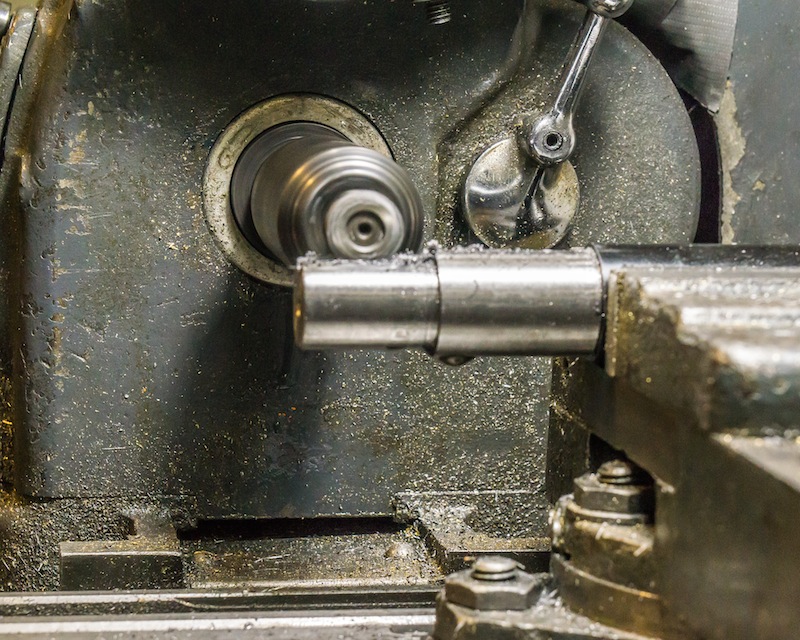
I mounted the blocks in a four jaw chuck to drill and bore the holes for the needle bearings.
The bearing was pressed into the block with at least a .001″ interference fit. The bearings will be lubricated from a hole in the end of the axle.
The photo above shows four drivers with the crank pins installed. In addition to pressing them in with a 12 ton hydraulic press, they are secured on the back of the wheel with a bronze washer and epoxy. The pins were turned to the Allen Models drawing for the consolidation pins with a few exceptions. The main drivers on 2-8-0s are the third set. The main drivers on 4-8-0s are the second set – longer and larger to accept the main rod attached to the pistons, as well as the side rods. I made the left side pins 1/4 inch longer to allow for changing the gauge from 7-1/4 to 7-1/2 inches and vice versa. Split bushings are mounted on the drivers in the background in the above photo. There will be similar bushings on the ends of the left hand axles.
The horizontal mill set up for milling and drilling set screw holes on the movable left hand drivers, for changing gauge.
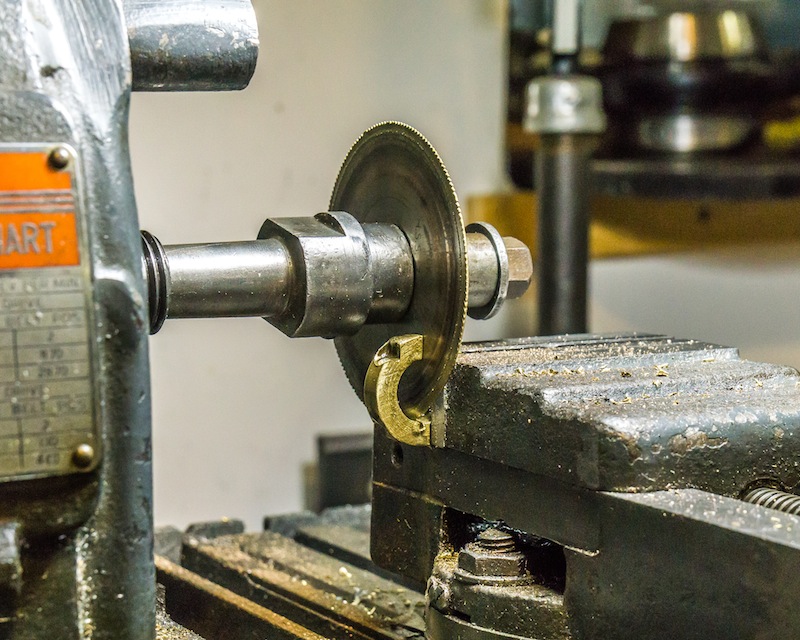
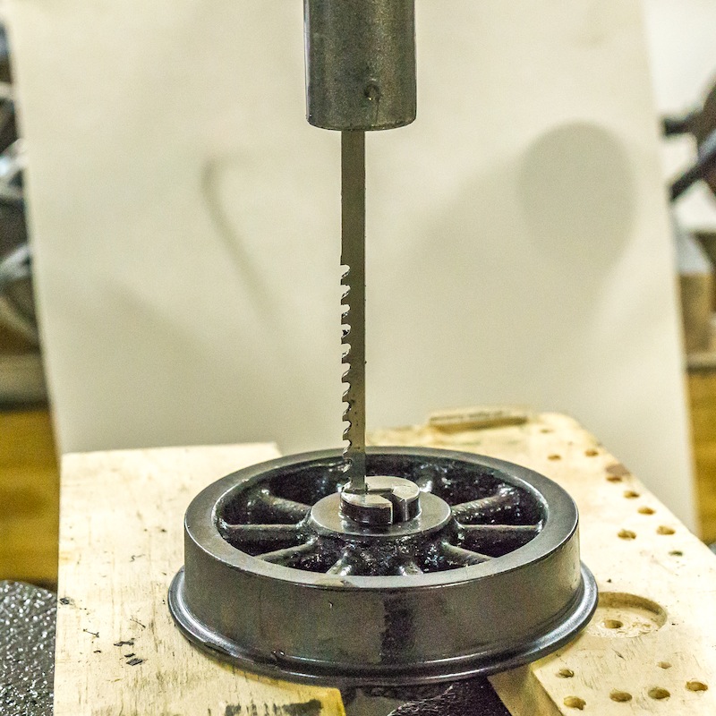
Sawing a gauge changing split bushing for one of the crank pins.
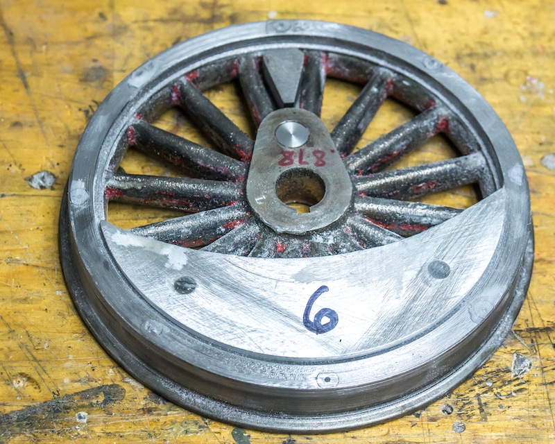
I was determined to use parts I already have, rather than buying new parts. The wheels I had were the correct diameter for the model I’m building, but four of them were too thin, none of them had cast in counterweights and the stroke was too short.
Previous articles in this blog deal with adding material to make the wheels thicker and making counterweights out of aluminum and epoxy. The remaining problem was the short crank length. I’m building a freight engine, not a race car. The stroke on the original Little Engines 4-4-0 was two inches. I needed a stroke of four inches to go with my two inch cylinder diameter.
I started by plugging the hole for the crank pin on the original wheels by pressing in a steel pin. I epoxied a triangular shaped piece of steel between the spokes where the new crank pin would be located.
I made long oval plates from 1-1/2″ x 1/4″ cold rolled steel. The ends were rounded on the mill using a rotary table.
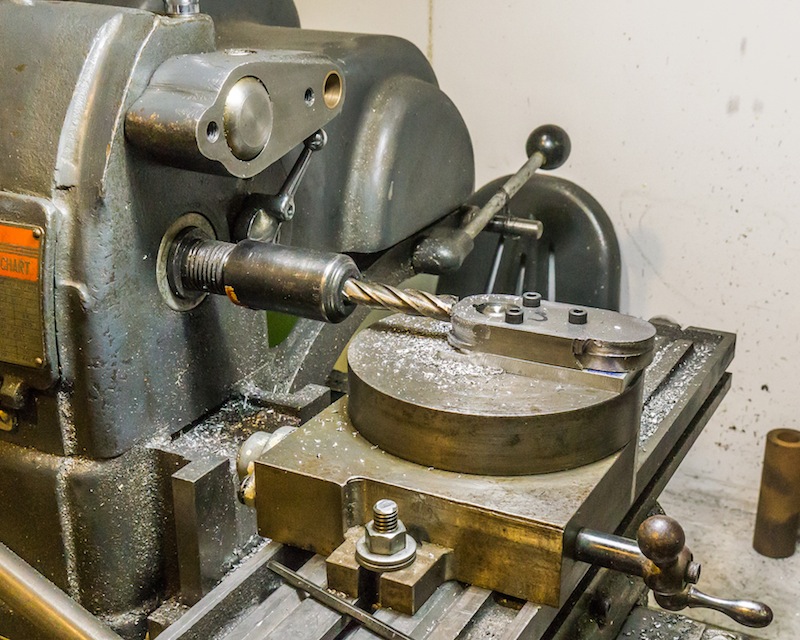
The plates were epoxied and screwed to the wheel. The wheels were mounted on the face plate, on the lathe. I took a light skim cut to ensure the plates were parallel to the back of the wheel and six wheels were close to the same thickness. The two blind main drivers were made 1/8″ thicker to match the thickness of the thicker counterweights. I made a fixture to drill and mill the new crank pin hole in the same location on each wheel. I had to ream the holes in my drill press because I do not have enough travel in the “Y” axis on my horizontal milling machine.
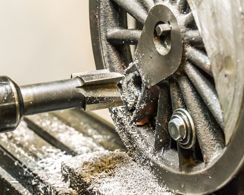
The last operation was milling a one inch diameter counter-bore on the back of each wheel at the crank pin location. The crank pins will be pressed in, but part of the press surface will be epoxy, so I will screw the pins in from the back with a large washer for added strength.
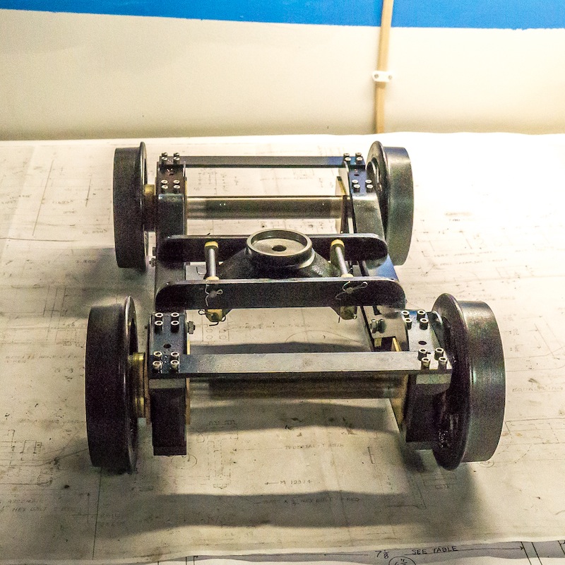
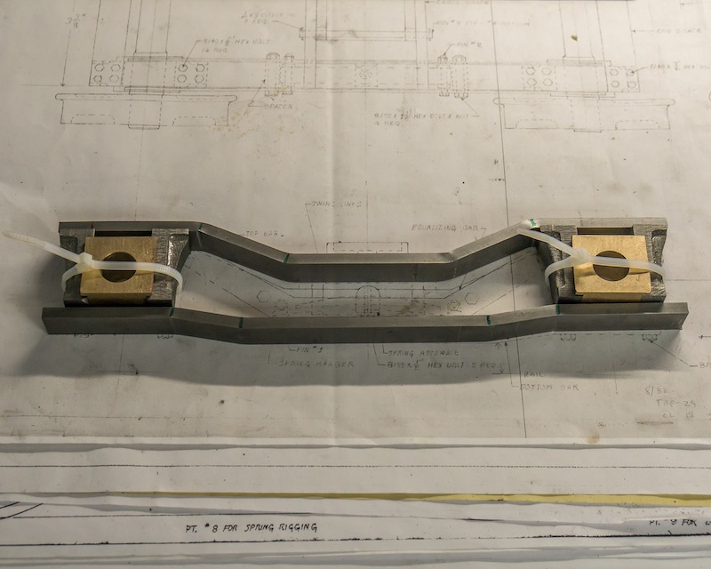
This photo shows the finished truck setup for 7-1/4″ gauge. Moving the brass bushings to the inside of the wheels on one side, makes the truck 7-1/2″ gauge. My plan is to make similar bushings for the drivers and crank pins. I don’t foresee changing gauge very often, but I want it to be possible without major surgery to the locomotive.
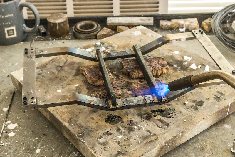
After bending up the frame it was necessary to braze the parts together.
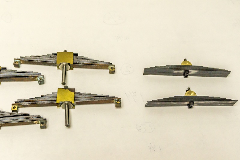
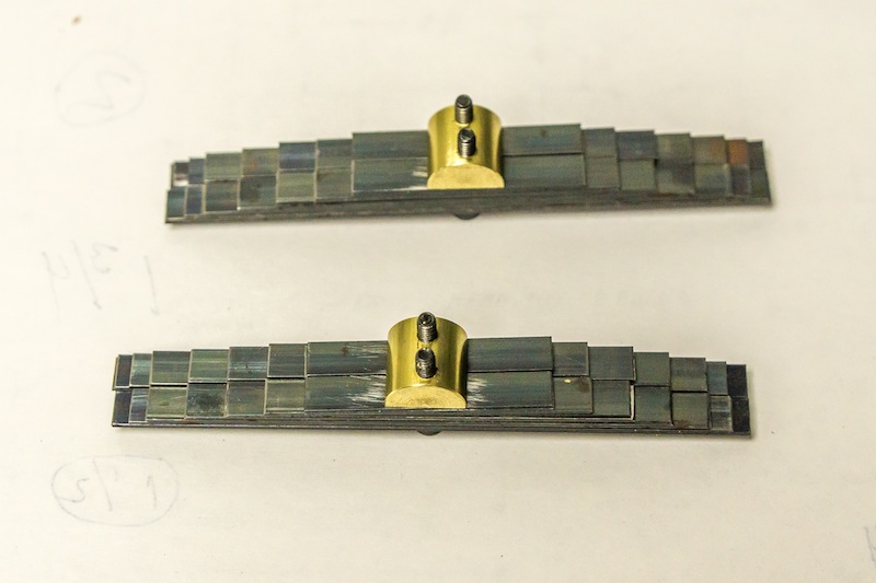
My parts engine had some leaf springs 1/4″ wide (left in photo). I made 1/2″ wide spring assemblies by using the narrow springs next to each other.
I pressed the axle onto the wheels on one side of the truck only. The wheels needed to be a keyed slip fit on the other side to accommodate changing gauge.
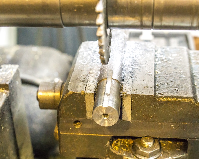
Milling the keyway on an axle.
Broaching a keyway in a wheel.
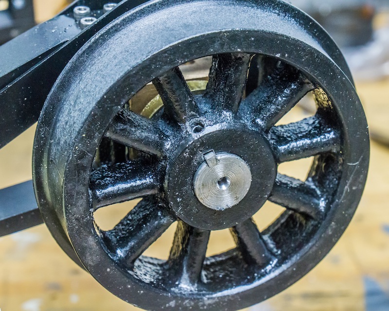
The photo above shows a #10-32 set screw on a wheel setup for 7-1/2″ gauge. I used two set screws, 90 degrees apart on both wheels.
The main side frames of the arch bar truck are made of 1/4″ x 3/4″ cold rolled steel. All I have to do is put some 10 and 25 degree bends in them.
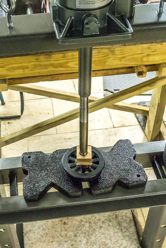
So I went to Harbor Freight and bought a 12 ton press. I needed it anyway for broaching keyways and pressing the wheels onto the axles.
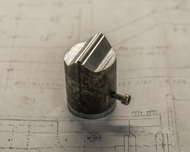
This is the tool I made to press down on the bar stock. I just happened to have a funky concave cutter, I picked up at an auction some time ago. This was the first time I’ve used it.
I made the receiver out of scraps. The two cylinders are 3/4″ 1144 stress proof steel cut from the ends of my axles. The vertical rectangles are square to the cylinders and will keep the bar straight when I press the angles.
The two photos above, show the arch bar setup in the press. I had made cardboard templates cut to the angles I needed, but I found it was easier to just go slow and check the parts often with a protractor.
If I pressed too much, it is easy to reduce the angle in a vise.
It was quite easy to bend the bars and only took a few minutes. I spent all afternoon making the tool and fixture.