4-8-0 Camelback Details

Lead Truck; Axles & Bearings

The machined axles are made of .75″ 1144 (stress proof) steel.

One end is .25″ longer to allow the gauge to be changed from 7-1/4″ to 7-1/2″ and vice versa. The back-to-back shoulders are set for 7-1/4″ gauge.

The bearing blocks are cast bronze. I mounted them in a four jaw chuck and machined one outside face; then bored the ID for a slip fit on the axles.

I made an aluminum “spider” to sit behind the bearing when I machined the second face parallel to the first face.

I used scraps of 1/8″ thick aluminum to protect the machined faces when I finished the ends to length.

The side slots were machined in the horizontal mill. The final operation was to drill a 1/16″ oil hole with a milled oil pocket on the top.

Finished axles, bearing blocks and bolsters.

4-8-0 Camelback Details

Lathe Trick – Tool Centering

Here is a neat trick I learned many years ago from an old tool maker.

Place a 6 inch ruler vertically between your tool point and something round mounted on the center line of your lathe. In this example, I used a dowel pin chucked in the tail stock.

You can see the ruler is leaning back. The tool needs to be lowered. When the ruler is perpendicular to the lathe bed, the tool will be on dead center (tangent to a circle). If the ruler was leaning forward, you would move the tool higher.

I am centering a boring bar in the above photo. You can use your work piece if it is a cylinder.

4-8-0 Camelback Details

Lead Truck Pedestals

These parts are cast iron. They were over .900″ square, and they had to go down to .750″ square. Unfortunately, they were cooled too quickly after they were cast and the iron was as hard as rock!!

Milling the parts square.

I started using high speed steel cutters on my horizontal mill. I was wearing down the cutters as fast as I was removing material until the cutters were polishing the metal instead of cutting. Steve Alley (Allen Models) offered to replace them with softer castings, but I had already spent a lot of time on them, and I bought a solid carbide end mill which made a big difference.

Milling with solid carbide.
Milling the pedestals.

After I got the castings milled to size, I cut them apart (each casting makes two pedestals).

After sawing the castings in half.

The next step was squaring the ends and milling the parts to length. Make sure you check your parts often with a machinists square.

Checking squareness.

There was a lot of material between the two parts, so I sawed the excess off with a band saw before final milling.

Too much material.
Sawing off extra material.

File the edges to finish the parts.

4-8-0 Camelback Details

Swing Bolster

This casting looks like a real bugger to machine, so I might as well do it now and get it out of the way. This is the part of the lead truck attached to the locomotive frame. The photos tell the story of the steps I used to machine this part.

Iron casting and drawing from Allen models.
I started by finding the rough center of the top boss.
This looks like a “safe” setup. Watch the fingers!
I left as much material as possible for a clamping surface.
Spot face on the bottom.
Interrupted cuts – slow speed; small bites!
Outside edges – take off just enough to clamp on.
Squaring the part.
Using an indicator to make the other side parallel to the first side.
Using an edge finder to establish the center of the part.
Center drill; drill; and ream to size.
By using a mill instead of a drill press, I could get both holes equidistant from the center and parallel to each other.
Machining the sides. I touched off the shaft to keep the hole in the center of the part.
Measuring setup.
Machining the top of the part to size.
Finished part.

This part was a bugger! I spent approximately twelve (12) hours machining it. Castings are always a challenge to hold and the many interrupted cuts require slow machining. I do not own a vertical milling machine. The horizontal mill works well and the dials are accurate. If you have any questions, please leave them in the comments below.

4-8-0 Camelback Details

Lead Truck Wheels, Finished

I had to modify the face plate to finish maching the spoked wheels for the lead truck, so I waited until the drivers were finished.

Face plate modified to mount lead truck wheels.

I drilled and tapped the center of the face plate for a 1/2-20 thread. I screwed in a pin I had turned to fit the ID of the wheels. I used a 1/4-20 SHCS for a drive pin and the wheel was held in place with a 1/4-20 screw and washers in the center of the pin.

Turning the 2 degree angle on the wheel tread.

I machined the tread to 3.750 inches. A taper of 2 degrees was machined on the tread with the compound. The radius at the base of the flange was machined at the same time.

Wheel reversed to finish the flange profile.

The wheel was turned around and the flange profile was finished.

12 wheels for the DL&W Mastodon.
4-8-0 Camelback Details

Counterweights

The drive wheels I’m using were cast without counterweights because they were designed for an early American type engine. I purchased aluminum blanks – 6 inch diameter discs; 0.080 inch thick for the back; and 0.125 inch thick for the front of the wheels.

Aluminum blanks and cast iron wheels.
Rear counterweight and spacers.

I cut the counterweights to shape on my band saw. I measured the thickness of each wheel and made appropriate length aluminum spacers for each wheel. The spacers were tapped for #5-40 screws on both ends.

Assembled counterweight – test fit before epoxy.
Rear blank and spacers epoxied in place.

I mixed West System high density adhesive filler #404 with Total Boat epoxy. I screwed the spacers to the back plates and epoxied the back assembly in place and let them harden. I screwed and epoxied the front plates on and mounted the wheels in an upright position (see photos). Use waxed paper to protect tools and the workbench from the epoxy.

Wheels mounted upright.
Filling the cavity between the counterweight blanks with epoxy.

I used a large garden syringe filled with epoxy and high density filler to fill the cavity between the counterweight blanks.

What a mess !!!!

The high density filler is composed of mostly powdered silica, so it is very difficult to sand off the excess epoxy. I was able to chisel and sand the backs of the wheels flat, so the wheels could be mounted in the lathe to machine off the excess epoxy from the front of the wheels and counterweights.

Wheels cleaned up.

I used a rotary burr in a flexible shaft tool to clean the epoxy off the spokes.

I mixed epoxy and filler to the consistency of thick peanut butter, to fill holes and gaps in the epoxy.

Filling holes with putty-like epoxy.

Once the wheels are painted they will look like fully cast wheels.

4-8-0 Camelback Details

Computers and CAD

My first home computer was a “286” a friend of mine built for me back in 1987. Not long after that I acquired a bootleg copy of Autocad for DOS. It was great designing HO model railroad stuff on the computer. I even had an early pen plotter that took 11 x 17 paper. I had to change pens manually, but I could make paper drawings in color!

Unfortunately, technology accelerated very fast in those days. Windows 95 came along and my Autocad program was soon obsolete along with the pen plotter.

I remember being very frustrated with those early versions of Windows. Programs left a lot to be desired and then there was the “blue screen of death!”

I tried an early distro of Linux – Suse. When it worked it was great, but when it didn’t my poor little brain did not compute! I gave up on it and went back to windows for a bunch of years.

I kept looking for a simple CAD program so I could draw 2d parts. The real world of design was embracing 3d CAD. The simple (cheap or free) CAD programs were either too simple or geared towards architecture or were impossible to learn.

About ten years ago I had the opportunity to purchase a second hand Mac Pro. I loved it! Bye bye Windows. However, the Mac got old and it was soon apparent, the firmware would not let me upgrade the OS past version 10.7.5. It was not long before I could not even get on the internet because even Firefox would not support the aging operating system.

I retired in 2015. A new Mac Pro was expensive! So I looked at Linux again. The early bugs are mostly gone and most of the distros work great. There is sophisticated open source software to do almost anything that can be done in Windows or on a Mac. So I am happily using Ubuntu 18.04 on a System 76 machine build to optimize the Linux OS.

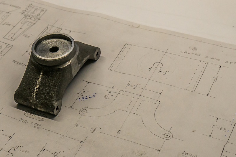
This week, I really needed to make a simple 2d CAD drawing. So I googled “open source CAD for Linux.” There are lots of programs to choose from and many reviews guiding a user through all the different options.

The first program I tried was FreeCad. It looks pretty impressive, but after trying to draw my simple drawing it became apparent it was going to be a very hard learning curve. No polar coordinates in the “sketcher” module and to create a mid-point, I had to construct it rather than hitting a button!

The second program I installed is the free version of Qcad. OMG, it works just like the old Autocad for DOS!!! I made my drawing in less than an hour without looking at any tutorials or help screens. I love it!

4-8-0 Camelback Details

Lead Wheels, 3rd operation

It is going to be four operations to finish these wheels. Since I machined the radius on the back of the flange, there was not enough material to safely clamp on using the six jaw chuck, so I will have to finish the front on a face plate.

Clamped on the flange, start of operation no. 3

The front diameter started at 4.435 inches. I took it down to 3.800 in this operation. The wheels will finish at 3.750 inches. It looks like it would take forever to take off that much material, but with a sharp brazed carbide tool, I could take off .040 per pass. It only took about 15 minutes per wheel to make a big pile of chips!

Rough turned to 3.800 inches.

I drilled the center out to 5/8 inch.

Rough drilling the center.

Finally, I used a single point boring bar to finish the center hole at 0.6875 inches.

Boring the center hole.
4-8-0 Camelback Details

Lead Wheels, 2nd Operation

Indicating the wheel in a 6 jaw chuck.

I mounted the first side in an adjustable six jaw chuck. I indicated the ID of the work hole to .001 inch.

Machining the back of the wheel.

I started by facing the wheel. The work hole is not concentric to the casting on the back side because of a slight mismatch between the cope and the drag when the wheel was cast. It looks good on the front side. I machined the OD down to 4.10 inches. The wheel finishes at diameter 3.750. This will allow a flange height of 0.175 inches.

Machining the back radius with a form tool.
4-8-0 Camelback Details

Lead Truck Wheels

I am using spoked wheels from Allen Models. I will be machining the wheels in three operations. I mounted the casting in a four jaw chuck. I tried to mount the casting so the outside edge of the spokes were running concentric to the lathe spindle.

Cast wheel mounted in the four jaw chuck.

The first operation will face the front of the wheel, drill a work hole in the center, and rough turn the OD to give me a surface to clamp on for the second operation.

Front face machined.
Drilling a 1/2 inch work hole in the center of the wheel.
OD machined concentric to the work hole.

I also machined a chamfer on the inside of the rim and on the outside of the inner hub.