4-8-0 Camelback Details

The Gauge Problem

We model 1/8 scale. Standard gauge in the real world is 56.5 inches. Divide that number by 8 and we get 7.0625 inches. That is 7-1/16 exactly! That is the correct gauge. Nobody uses it anywhere!

When the hobby started in merry old England 7-1/4 inches became the standard. All the drawings were in fractions, so if you are using an old wooden yardstick to measure everything, I guess that makes sense.

Most 1/8 scale railroads around the world use 7-1/4 inch gauge, including the northeastern part of this country. Even Walt Disney built his railroad in California to 7-1/4 gauge. So why the f*** is most of the USA using 7-1/2 inch gauge????

The “why” doesn’t really matter anymore. The problem exists and we are all forced to deal with it.

If you never ever travel with your trains, different gauges don’t matter, until you want to sell your train. You can run your trains on your home track to your hearts content. This hobby is very social. We like to take our trains to other tracks to run. My 7-1/4 inch gauge home track is the Finger Lakes Live Steamers in western New York State. I can take my trains to Mud Creek (Buffalo), Adirondack (Saratoga Springs), Long Island, Pioneer Valley or Waushakem (MA), New Jersey, Pennsylvania and a few other tracks in the Northeast and southern Canada.

But suppose I want to go to Florida in the winter; or Ohio – just five hours west of my home. There are some nice tracks in Michigan and the Midwest. Sorry they are all 7-1/2 inch gauge.

The Northeast is densely populated and the live steam clubs are old. Finger Lakes celebrated their 50th anniversary this year. There are hundreds or maybe even thousands of engines and cars gauged to 7-1/4 inch. Then there is the track. Finger Lakes has 12,096 feet of 7-1/4 inch gauge track as of this writing along with over 80 switches. If we figure an average of 3-1/2 ties per foot with 3 screws per side; to re-gauge the track to 7-1/2 inches, we would have to move 127,008 screws in 42,336 ties! Of course if we had to turn the ties over or replace them, just double the number of screws. I don’t think anyone would be anxious to re-gauge their railroad.

I have heard of a few railroads that accommodate both gauges, but it requires some pretty precise track work, especially on the switches. If it were really feasible, I think there would be more than just a few tracks out there.

So, the solution to running on both gauge tracks is to make dual gauge trains.

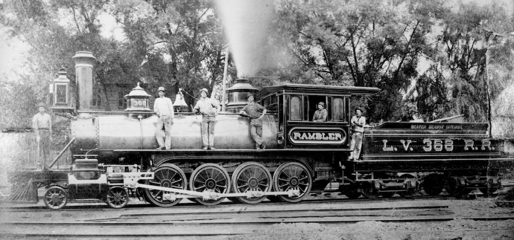
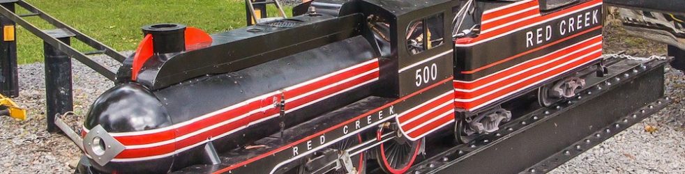
The big advantage for dual gauge equipment is when the time comes to dispose of our trains. The “500,” my 4-4-0, was built in 1957 by Jim Turnbull of Montreal. I am the 6th(?) owner of the engine and it still runs! Obviously, our equipment will out last all of us. The “500” is 7-1/4” gauge only. Changing the gauge would require major surgery including new axles. My Shay, on the other hand, has axles long enough for 7-1/2” gauge with a spacer on the end. By removing the left hand side frames, the gauge can be changed in just a few hours. Recently, a sale was made via Discover Live Steam of a 7-1/2” gauge Big Boy to someone in New Zealand. They had it re-gauged to 7-1/4” gauge. What a nightmare that must have been, unless the builder made allowance for such a change! When the time comes to sell, whether by you or your estate, if allowances for easy gauge change have been built into the equipment, anyone in the world is a potential buyer.

My buddy Alan Francis designed a really slick way to easily change gauge on equipment with an outside frame.

Dual Gauge Design by Alan Francis.

He cuts two grooves in the axle for retaining rings. A hub on the inside attached to the wheel, allows the wheel to slide from one gauge to the other. Screws on a locking collar, lock the wheel in place at the desired gauge. He uses a key when the axle is driven (diesel locomotive). The difference of a 1/4 inch is not noticeable when looking at the truck.

Dual Gauge Design by Alan Francis.

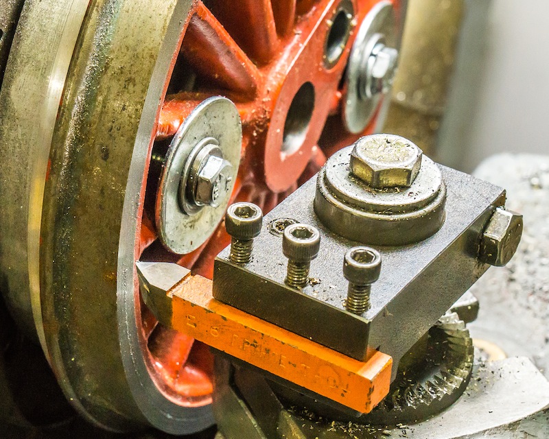
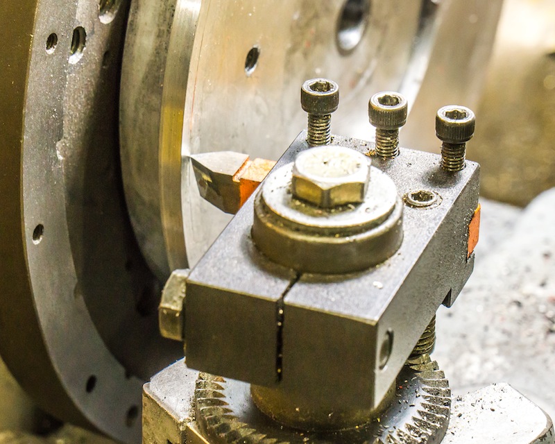
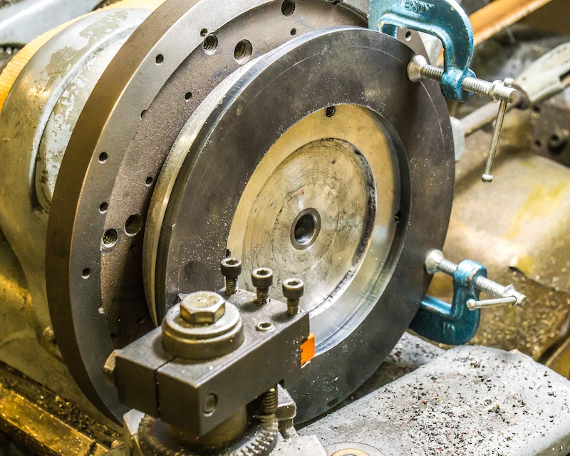
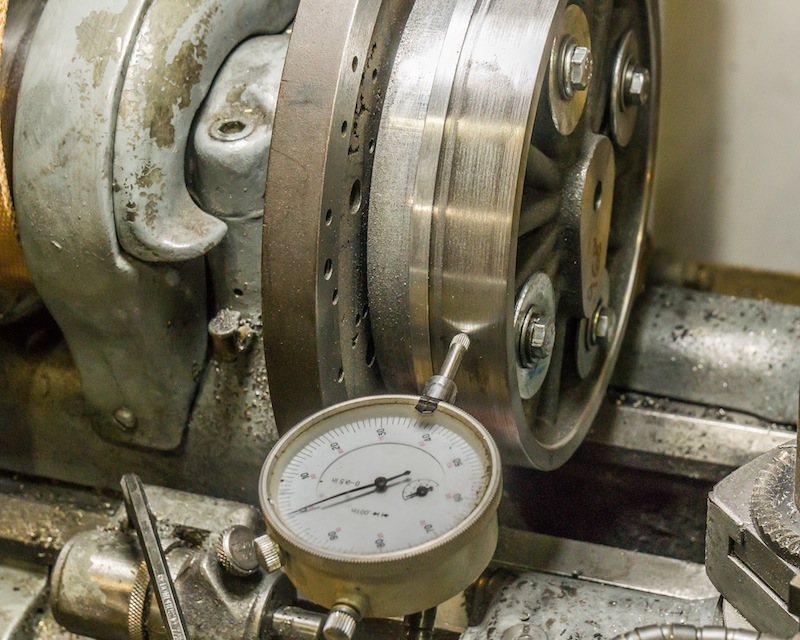
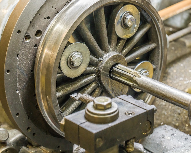
Steam locomotives usually have inside frames. That makes changing the gauge a little more challenging. The frames have to be narrow enough for 7-1/4 inch, but the cylinders have to be spaced wide enough for 7-1/2 inch gauge. I have also seen engines with a tire, able to slide in and out on a wheel.

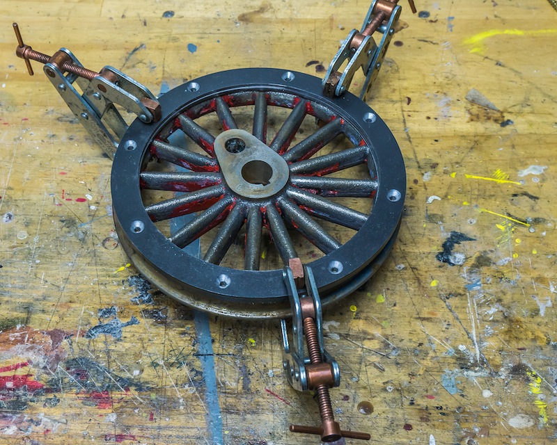
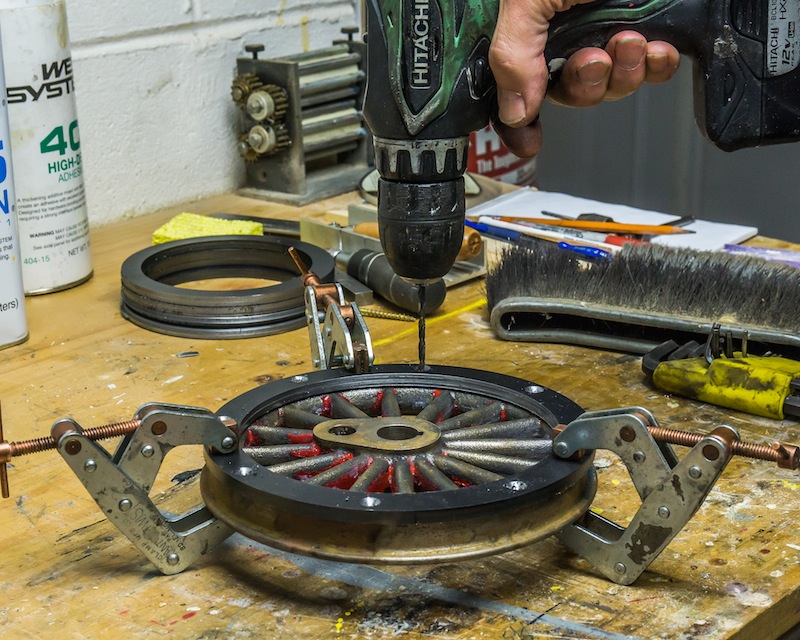
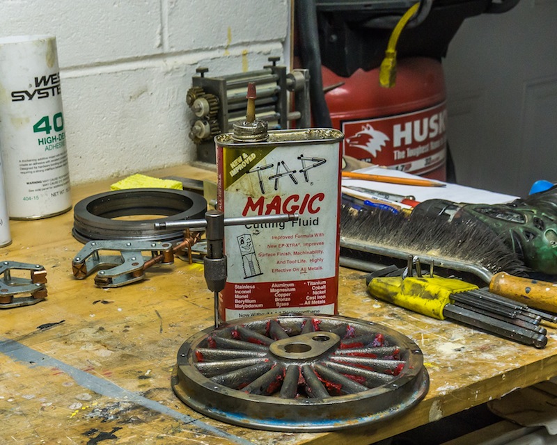
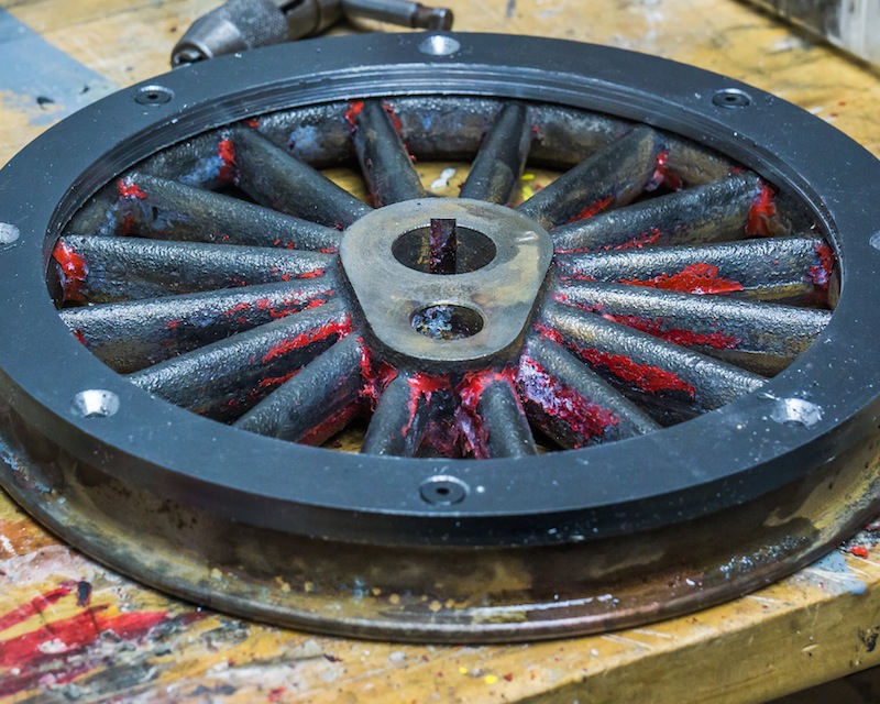
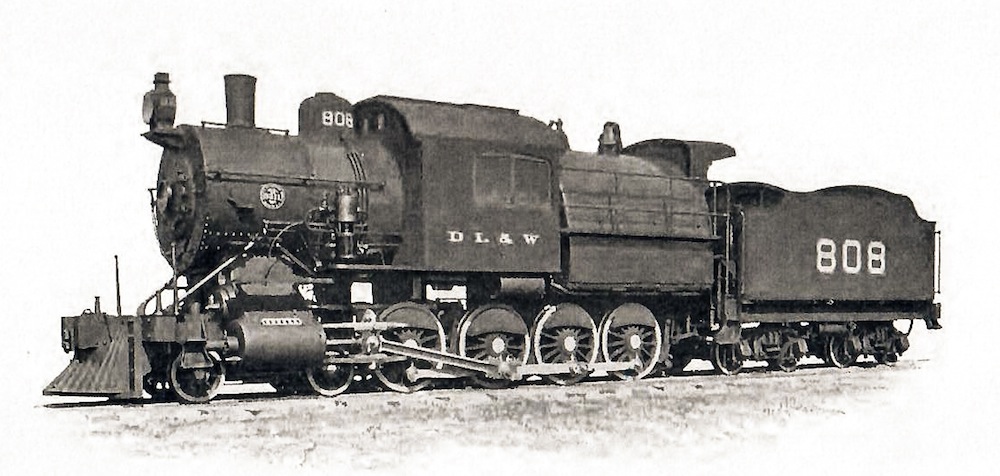
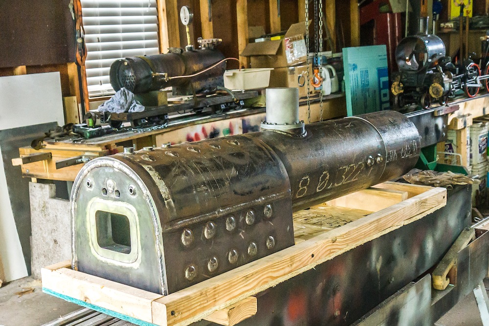
Stay tuned to see how I solve this problem on my 4-8-0.

4-8-0 Camelback Details

Wheel Thickening, Part II

Plate ready to match drill.

After trimming the plates to size, I used a counter sink on all the drilled holes to accept a #6-32 x 3/8 flat head screw. A machine screw reaches full strength in just 2-1/2 turns, so the screws do not need to be very long. After machining the face of each wheel flat, I clamped a ring to each wheel, lining the holes by eye.

Match drilling hole locations.

The plate was already drilled with #26 clearance holes, so I used that drill to just spot the locations on the cast iron wheel. I put a center punch mark next to one hole on each plate. I kept the plates with their mating wheel and kept track of where the first hole was on each. I then drilled the castings with a #35 tap drill to a depth just short of the flange.

Tapping #6-32 threaded holes.

I carefully tapped all the holes by hand (No, I did NOT break a tap).

Test fit the parts before final assembly!
Epoxy resin.

I have been using West System epoxy for many years. Unfortunately their price has been going up lately. I had recently run out, so I bought Total Boat epoxy instead for just about half the price of the WS epoxy. As near as I can tell the products are identical. Even the pump handles appear to have come out of the same mold! The only difference is the color of the plastic. Make sure all the parts are cleaned of oil and tapping fluid before gluing and screwing the parts together.

Epoxied part, left; finished part, right; casting, rear.

I let the epoxy set and harden over night. I mounted the epoxied wheel on the face plate and used an indicator to make sure the circular runout was less than .005 inch. I machined the inside edge, the outside and the face to the same dimensions as the all cast wheels. I haven’t decided how the centers will be built up yet. One step at a time.

Wouldn’t it have been easier to just buy 4 new castings and make all 8 wheels exactly the same?? Yeah, it would have, but I am retired, I have plenty of time, I want to use my collected stuff, and I would rather spend my budgeted hobby money on things I don’t already have in a box somewhere.

4-8-0 Camelback Details

Wheel Thickening Part 1

The four original drive wheels from the parts engine had been machined to a thickness very close to the minimum of 0.750 inch. The four castings I purchased cleaned up at 0.900 +/-0.005 inch. I decided to bolt and epoxy a plate onto the front of the thin wheels and machine them to match the 0.900 thick wheels. Luckily, I found 1/4 inch thick washers – 7 inch OD x 4-1/2 inch ID – made of A36, on Ebay for only $7 a piece. They appear to have been cut out of flat plate with a laser.

Marking the center line of the bolt circle.

I mounted one of the thin wheels on a face plate on my lathe and indicated it to less than 0.005 inches, circular runout. I took a light face cut and marked the center of the face, turning the face plate by hand. The diameter of the bolt circle measured 6-7/16 inches.

Marking the center line on the face plate.

I then marked the face plate without moving the tool in or out. Finally, I carefully marked the same line on one of the washers.

Marking the center line on a part.

There are probably 1,001 ways to lay out a bolt circle on a part. This is how I did it.

Marking the center of 2 holes, 180 degrees apart.

The first step was to use a center gauge on a combination square to mark 2 holes 180 degrees apart. I then consulted Machinery’s handbook for the formulas I needed to find the rest of the holes.

Using trigonometry to find the length of chords for 8 holes.
Marking 4 holes 90 degrees apart.

Once I determined the length of the chord for the 2 holes 90 degrees to the first two, I used calipers and dividers to carefully mark the locations. I then calculated the length of the shorter chord for the holes at 45 degrees. I carefully center punched the locations of all 8 equally spaced holes.

Drilling all 4 parts.

I used a center drill and then a Number 35 tap drill for 6-32 threads. I placed one part on the faceplate, lining up the holes with the scribed circular line. I clamped the part in place and match drilled the 8 holes. I put a small mark next to one hole and a corresponding mark on the faceplate, in case the holes were not really equally spaced. I tapped the faceplate for 6-32 threads and then drilled out the holes in the parts with a Number 26 clearance drill. The holes DID come out equally spaced!

Four parts drilled.

There is a lot of extra material on the ID of these washers. I cut a trepan 1/8 inch deep on both sides of the parts mounted on the faceplate.

Cutting the trepan.
The groove before breaking the center out.
Washer ready to be applied to the wheel. (Scrap center on left)
4-8-0 Camelback Details

Drive Wheels

I had four wheels from the parts engine I originally purchased. Unfortunately, they were machine to a width of .760 – very close to the minimum of .750 inches. I will be attaching a plate to make them thicker (more on that in a future post).

I was able to purchase four more castings from Little Engines (isn’t it great they are still in business!!!). I faced and turned the back of the wheels in 2017. The OD would become the flange on the finished wheel. I had a pin mounted in the face plate to locate the wheels on the small hole I had drilled in each wheel. Don’t do it this way – it was stupid on my part! The smarter way would be to mount the pin in the tail stock, so once the back of the wheel is clamped to the face plate, the front can be turned and the hole in the center bored concentric to the OD at the same time. I guess I just miss using an indicator!

The photo above shows turning the OD of a blind driver. Only one set will be blind.

I made the OD of the tread at the intersection of the radius and the angle of the flanged driver 6.750 inches. That is the dimension of the center of the OD on the blind driver.

I set the compound to 2.5 degrees and cut a chamfer 5/32 deep on both sides of the blind drivers.

After I removed my stupid pin from the faceplate and mounted it in the chuck on the tailstock, I had to indicate the wheel back into position to bore the center to size.

I drilled the center out using progressively larger drills up to 11/16 inch.

I used a single point brazed carbide boring bar to make the hole .745/.747.

The hole was finally reamed to .750 inch.

4-8-0 Camelback Details

D.L.&W. or C.R.R. of N.J. Camelback – (4-8-0)

Brooks Locomotive Works, 1899

How did I choose to build a live steam model of this engine?

It started several years ago when I purchased a partially build Little Engines (early) 4-4-0 from a friend. You know the engine – red wheels, big brass balloon stack and a tiny copper boiler. I love 19th century railroad equipment. However, I knew a tiny little boiler on a small engine in 1/8 scale would not have much power. It might pull me up a 1-1/2% grade, but not with a heavy train in tow. So I started researching possible alternatives.

The drive wheels scale up to 54 inches. That size is more typical for a freight engine later in the century than most of the larger 4-4-0s. A consolidation would be a good choice – I could even model the original 2-8-0 built by Baldwin in 1866 for the Lehigh and Mahanoy Railroad.

Lehigh Valley

I soon discovered the Lehigh Valley built a number of mastodons (4-8-0). Many of these engines were converted to camelbacks around the turn of the century.

Lehigh Valley 4-8-0 camelback

I started planning to build one of these engines. I sent Marty Knox a drawing for a camelback locomotive boiler drawn by my friend Alan Francis. However when Marty actually started to make the boiler he did not like the Lehigh Valley firebox design. The 45 degree sloping side sheets made the steam space above the crown sheet very cramped and it reduced the number of tubes he could fit in the boiler. He chose to make a “fat” firebox as seen on the Delaware Lackawanna & Western Railroad and the Central Railroad of New Jersey engines. Both railroads had nearly identical locomotives built by Brooks in 1899.

Boiler made by Marty Knox (Ridge Locomotive Works)

I took delivery on the boiler this summer (2019), so now I start building the engine to fit the boiler.

4-8-0 Camelback Details

My Live Steam History

I joined the Finger Lakes Live Steamers in 1991. My first project was a well used Cli-Shay I picked up from another member of the club. It had been worked on by a number of owners over the years and its plumbing was a bit of a nightmare. I did get it running, but not for long. The steel tubes in the vertical boiler had been dissolving over the years and it was not long before the boiler developed a number of leaks. The engine was dismantled.

My Cli-Shay taken in the mid 1990’s

I decided to build a more realistic early Shay using as many parts from the old engine as possible. The Shay I would eventually build, only used the wheels from the Cli-shay!

I knew building a live steam engine from scratch was going to be a multi year build, so I decided to build a (quick and easy) electric logging speeder, so I would have something to play with while I worked on the live steamer. I found a couple of 12 volt DC motors at an industrial surplus vendor. Each one powered a wheel set using a toothed belt and sprockets. Power was supplied by two 12v deep cycle marine batteries and I purchased a 4QD controller from England. The body was made of plywood and it was painted bright orange. I mounted a boat seat on a short flat car and in less than a year I had a toy I could ride around the club’s track.

My Mom driving my speeder, late 1990’s

In 1996, the Village Press published the book, “Logging with Steam’ by W.M. Harris based on a series of articles by the same author in Live Steam magazine. The book featured plans and a how-to-make article, building the Mich-Cal Shay in 1-1/2 inch scale to run on 4-3/4 inch gauge track. Perfect! I’ll just scale the plans up for 7-1/4 inch track and I’ll have a big narrow gauge live steam engine. Little did I know when I started building in 1997, the engine would not actually run on steam until 2018!

Running my 0-4-0. Jack Wylie looks on in the background.

Other projects and life in general got in the way. I purchased a one-inch scale 0-4-0 in working condition built by my friend Ed McConnell, somewhere around the turn of the century. In 2004 and 2005 I was unfortunate to develop DVTs in my left leg. Sitting cross legged on a flat car behind a 4-3/4 inch gauge engine was all of a sudden impossible. In 2006 I traded that running engine to my friend Rick Rubino for a large 1-1/2 inch scale 4-4-0 that needed a little work.

It took about three years to rebuild the American to working condition. The engine was originally built in 1957 by Jim Turnbull of Montreal (number 13 of 36 engines he built). The locomotive is constructed from Little Engines parts. It is basically their pacific (4-6-2), but missing the front driver set and the rear trailing truck, with a shortened boiler on top.

Running the “500” for the first time in 2009

The engine was built for Howard Crotty, the first president of the Pioneer Valley Live Steamers in Massachusetts. Howard still owned the engine in 1965 when it appeared in an issue of Model Railroader magazine. Carl Hoffman of Kitchener (or Waterloo?), Ontario was the next owner. The engine appeared in an article about his track in a 1975 issue of Modeltec magazine. It was sold to a Frenchman in Canada, who owned it for two years before selling it to Wayne McFarland of Toronto.
My friend Rick Rubino of Fairport, NY, purchased the engine in the mid 1990’s from Wayne who had been pulling people in a park in the Toronto area for some time.

I decorated the freelanced 4-4-0 as Chicago and Illinois Midland No. 500. That railroad had the last three 4-4-0s built by Baldwin for domestic use. They were big and closely resembled my engine. I started running the engine in October 2009. By 2017 it was showing its age. The running gear was worn out and the front tube sheet of the original copper boiler was leaking.

Meanwhile, I moved to a new house in 2014 and was able to retire in 2016. The Shay had been worked on sporadically over the years since it was started. When I moved into my new house, I decided I should really make a push to finish it. I got the engine and drive train running on compressed air on December 18, 2015. The engine finally carried me around the club track on July 28, 2018. I did have a few problems with the engine, needing some reworking here and there but as of this writing (September 15, 2019) the engine is running fairly well.

4-8-0 Camelback

About me…

My Mom called me a “train brain.” My favorite toys were trains and the stories I wanted to hear were all about trains. So when I became an adult, model railroading was a natural hobby for me. I started by building an HO scale empire in my basement. It was a freelance endeavor because I had so many different (railroad) interests. I loved camelback steam engines from the northeast anthracite railroads; but I also liked heavy electrics running under catenary. So my miniature empire featured both.

After a dozen years I was introduced to live steam trains big enough to ride on. I joined the Finger Lakes Live Steamers, located in upstate New York. I soon discovered there is not enough time to do everything. The HO layout was pushed to the back burner as I acquired machine tools to make parts for bigger trains. Eventually the HO empire was torn down and most of the little trains I had collected were sold.

My other hobby when I was young was collecting rocks and minerals. At some point I started cutting gemstones and making jewelry. By the time I was in high school I was faceting gems. After a couple of years at a community college I needed to decide on a career path. It was the early 1970s and the craft movement was in full swing. I was accepted to study jewelry design at the School for American Craftsmen at Rochester Institute of Technology where I earned a Bachelor of Fine Arts degree. I worked in the manufacturing of fine jewelry for several years, but I soon discovered I could make more money and get better benefits in the manufacture of steel parts (Tool and Die shops). I programmed and ran very early CNC machines in the 1980s. Somehow I fell into inspecting the quality of machined parts. I became a Quality Assurance Manager in 1987. Most of my career was centered around metal parts, but when I retired in 2016 I had been working in the quality of optical glass.

I am primarily writing this blog for myself to document the building of my next engine and a few other live steam projects. If others want to follow my progress, that’s great. I plan to update the blog on a fairly regular schedule.